Hydraulic pump, in particular a fuel pump

A technology of hydraulic pumps and fuel pumps, which is applied in the field of hydraulic pumps and can solve problems such as wear, energy consumption, and high energy loss

Active Publication Date: 2012-09-05
OMT OFF MEC TORINO
View PDF6 Cites 1 Cited by
  • Summary
  • Abstract
  • Description
  • Claims
  • Application Information

AI Technical Summary

Problems solved by technology

[0007] Despite its unquestionable simplicity, the regulation strategy exhibits significant disadvantages
[0008] The first mode of regulation is very energy-intensive due to the high energy losses caused by the resulting laminar flow of fluid
[0009] The second mode of regulation presents a major problem with wear associated with cavitation induced in the fluid at the pump inlet

Method used


Image

  • Hydraulic pump, in particular a fuel pump
  • Hydraulic pump, in particular a fuel pump
  • Hydraulic pump, in particular a fuel pump

Examples


Embodiment Construction

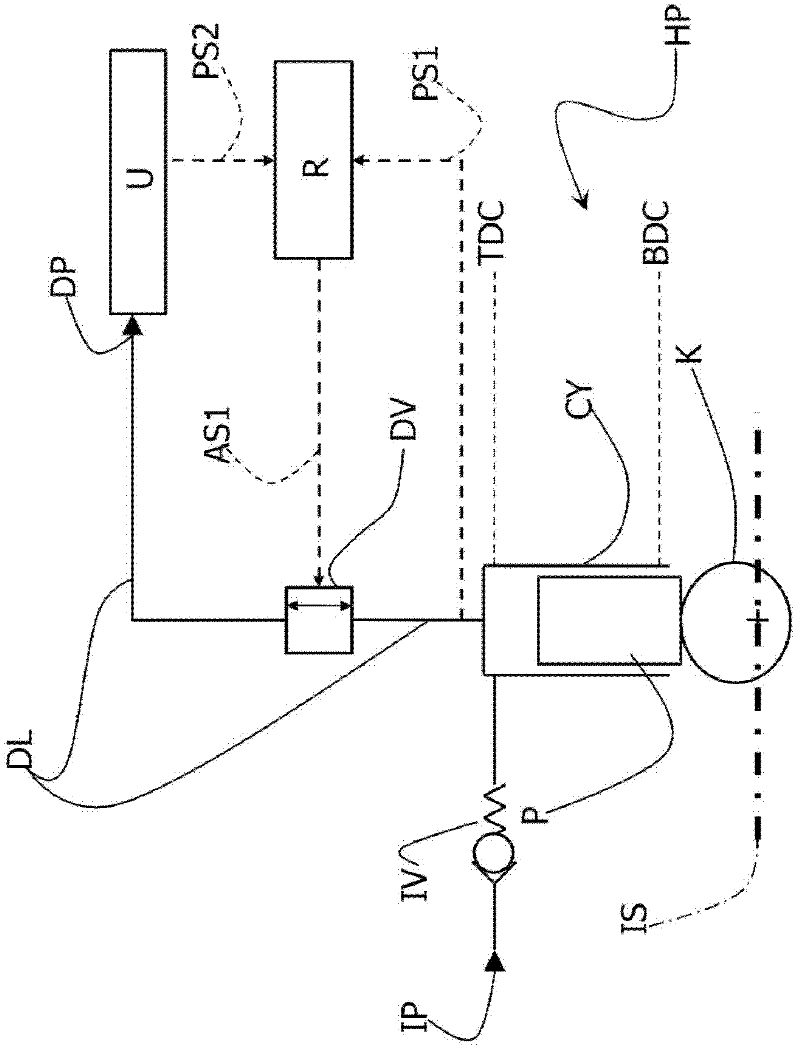
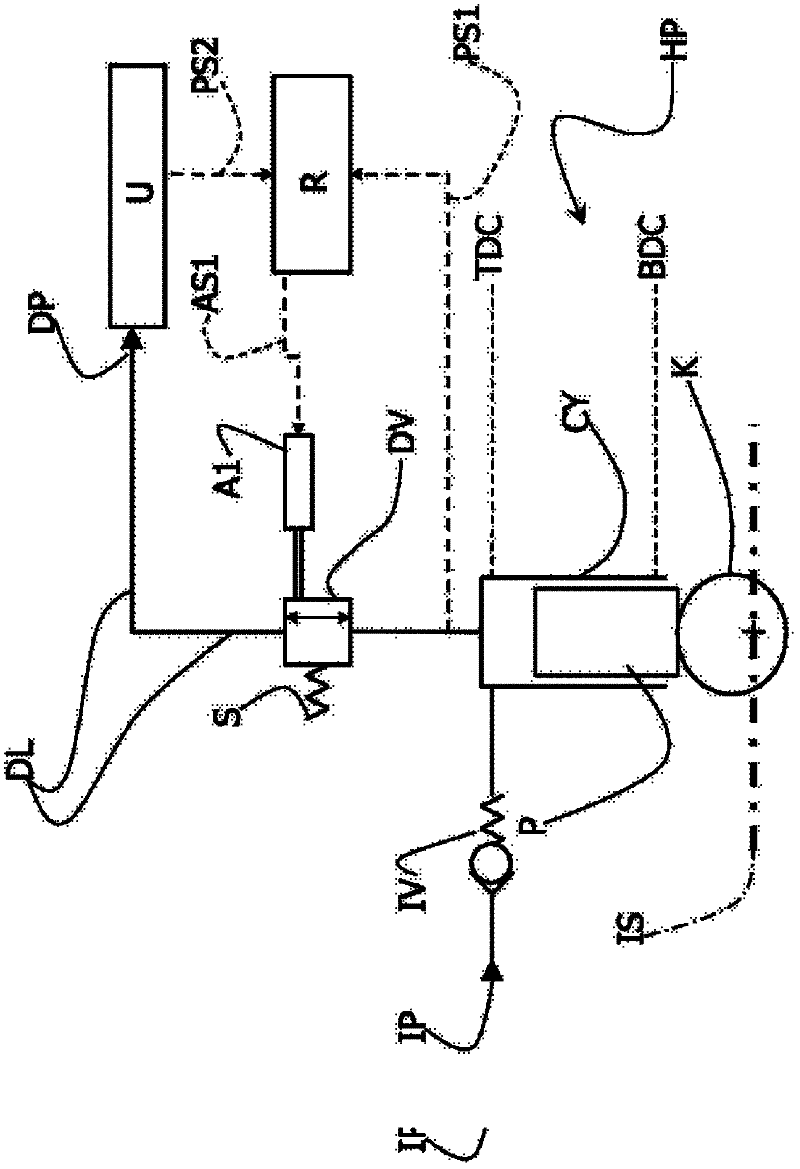
[0018] exist figure 1 , the reference sign HP designates hydraulic pumps according to different embodiments of the present invention. The pump HP comprises an inlet IP, an outlet DP and at least one cylinder CY in which a piston P is reciprocated by a mechanism K, such as a cam or crank mechanism, which in turn is actuated by an input shaft IS. Each piston P reciprocates between top dead center TDC and bottom dead center BDC.

[0019] As is known, the inlet IP is arranged in communication with the inlet port environment (not shown) and is in fluid communication with the cylinder CY through the inlet valve IV.

[0020] Furthermore, the cylinder CY is in fluid communication with the outlet DP via a delivery line DL on which a delivery valve DV controllable by means of an adjustment assembly R is arranged.

[0021] Delivery valve DV is movable between an open position arranged to allow fluid flow between cylinder CY and outlet DP and a closed position in which said fluid flow i...


PUM


Abstract

A hydraulic pump (HP; 1), in particular a fuel pump, comprising: - an intake port (IP; 2), - a delivery port (DP; 4), provided for hydraulic connection to a user (CR), - at least one cylinder (CY; 20, 22, 24), movable within which is a corresponding piston (P; P1, P2, P3), wherein the piston has, during the operation of the pump (HP, 1), a reciprocating motion between a top dead centre (TDC) and a bottom dead centre (BDC), - a delivery valve (DV; 26, 28, 30) for each cylinder (CY; 20, 22, 24) hydraulically connected thereto, movable between a closed position and an open position, wherein in the open position the delivery valve (DV; 26, 28, 30) is arranged for enabling a flow of fluid between the cylinder (CY; 20, 22, 24) and the delivery port (DP; 4), and wherein in the closed position the delivery valve (DV; 26, 28, 30) is arranged for blocking a flow of fluid between the cylinder (CY; 20, 22, 24) and the delivery port (DP; 4). The hydraulic pump (HP; 1) comprises a regulation assembly (R; 39, 40, 42, 43, 44, 46) which, when a threshold pressure (p REF ) in a user (U; CR) hydraulically connected to said delivery port (DP; 4) is exceeded, is arranged for keeping the delivery valve (DV, 26, 28, 30) in the open position during at least part of a movement of the piston from the top dead centre (TDC) to the bottom dead centre (BDC) and enabling a reflux of fluid from the delivery port (4, DP) to the cylinder (20, 22, 24).

Description

technical field [0001] The invention relates to a hydraulic pump, especially a fuel pump. In particular, the invention relates to improvements in providing flow regulating means for hydraulic pumps. Background technique [0002] In the technical field of hydraulic pumps, in particular fuel pumps, it is necessary to regulate the flow rate of the fluid delivered by the pump to the consumer substantially independently of the rotational speed of the pump shaft. [0003] In particular, in the field of compression-ignition internal combustion engines, whether they are engines for road vehicles or large stationary engines for marine use, all known solutions employ especially fuel pumps and pressurized fluid reservoirs (commonly called "common rail"), and basically obtains the regulation of the flow delivered by the pump to the common rail in two different ways: [0004] - through the regulating valve, which superimposes the excess flow delivered by the pump, which is not consumed...

Claims


Application Information

Patent Timeline
Patent Type & Authority Applications(China)
IPC IPC(8): F02M37/12
CPCF02M59/462F02M59/365F02M63/0029F04B49/08F04B49/22F04B49/246F04B2201/06012F04B2205/05F04B2205/06
Inventor 克劳迪奥·内格里
Owner OMT OFF MEC TORINO
Why Eureka
Try Eureka