Ring spinning machine having a false twist device

The invention relates to a ring spinning machine and a technology for ring spinning, which can be applied to continuous winding spinning machines, spinning machines, open-end spinning machines, etc., and can solve the problem of high cost, reduce energy consumption, and reduce end breaks. risk reduction effect

Inactive Publication Date: 2012-09-05
MASCHINENFABRIK RIETER AG
View PDF10 Cites 17 Cited by
  • Summary
  • Abstract
  • Description
  • Claims
  • Application Information

AI Technical Summary

Problems solved by technology

Therefore, the cost of eliminatin

Method used


Image

  • Ring spinning machine having a false twist device
  • Ring spinning machine having a false twist device
  • Ring spinning machine having a false twist device

Examples


Embodiment Construction

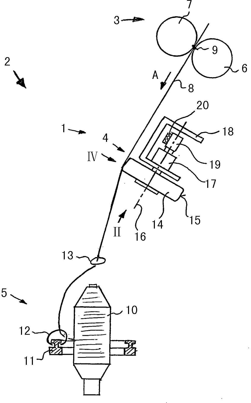
[0019] in figure 1 In this, a very schematic view of the spinning station 1 of the ring spinning device 2 is shown. The spinning station includes a drafting unit 3, a false twisting device 4 and a spindle 5 for a ring spinning machine. Only the front roller pair 6 including the lower roller 6 and the upper roller 7 pressed on the lower roller 6 is displayed in the drafting unit 3. The drafting unit 3 may include more roller pairs (not shown) in a known manner, which are used to stretch the fiber bundle 8 from staple fibers to the required fineness. The fiber bundle 8 is fully stretched at the clamping line 9 of the front roller pair 6 and 7 and is conveyed along the conveying direction A to the spindle 5 for the ring spinning machine.

[0020] The spindle 5 for a ring spinning machine includes a bobbin 10 that winds the twisted fiber bundle 8 into a yarn. The spool 10 is rotatable. The spinning ring 11 and the traveler 12 are provided on a spindle 5 for a ring spinning machine...


PUM


Abstract

In a ring spinning machine having at least one spinning station (1) that contains a drafting system (3) and a ring spindle (5), a false twist device (4) is arranged between the drafting system (3) and the ring spindle (5). A fibre strand (8) to be rotated can be placed laterally against the false twist device (4). The false twist device (4) comprises at least one rotatable disc (14, 24, 25, 26, 28, 29) having a friction surface (15) for a fibre strand (8). The fibre strand (8) can be guided by two adjacent discs (14a, 14b, 25, 26, 28, 29), which are arranged with a centre distance that is less than the disc diameter.

Description

Technical field [0001] The present invention relates to a ring spinning device, which includes at least one spinning station having a drafting unit and a ring spinning machine spindle, wherein a false twisting device is provided on the drafting unit and the ring spinning machine. Between the spinning machine spindles, the fiber bundle to be twisted is located on the side of the false twisting device. Background technique [0002] Japanese published patent JP62-231039 A discloses a ring spinning device of this type. The false twisting device includes a perforating roller on which the fiber bundle to be twisted transferred from the drafting unit can be placed. The fiber bundle passes through the circumferential surface of the perforated roller. The rotation axis of the perforation roller is arranged in parallel with the fiber bundle. The suction device is arranged inside the perforated roller. The suction device sucks the fiber bundle to the surface of the perforated roller. T...

Claims


Application Information

Patent Timeline
IPC IPC(8): D01H1/02D01H1/11D01H7/92D01H5/28D01H4/12
CPCD01H1/02D01H1/11D01H7/923D02G1/082
Inventor G·斯塔莱克
Owner MASCHINENFABRIK RIETER AG
Why Eureka
Try Eureka