Combine harvester

一种联合收割机、机体的技术,应用在收割机、切割器、机械设备等方向,能够解决联合收割机行驶性能降低等问题,达到防止行驶性能的降低、防止飞扬、耐久性提高的效果

Active Publication Date: 2012-09-12
YANMAR POWER TECHNOLOGY CO LTD
View PDF5 Cites 4 Cited by
  • Summary
  • Abstract
  • Description
  • Claims
  • Application Information

AI Technical Summary

Problems solved by technology

In particular, when the combine harvester is running in wetlands, since a large amount of mud and the like adhere to the exhaust device, the amount of mud and the like that intrudes into the exhaust device also increases, so there is a problem that the running performance of the combine harvester is reduced.

Method used


Image

  • Combine harvester
  • Combine harvester
  • Combine harvester

Examples


Embodiment 1

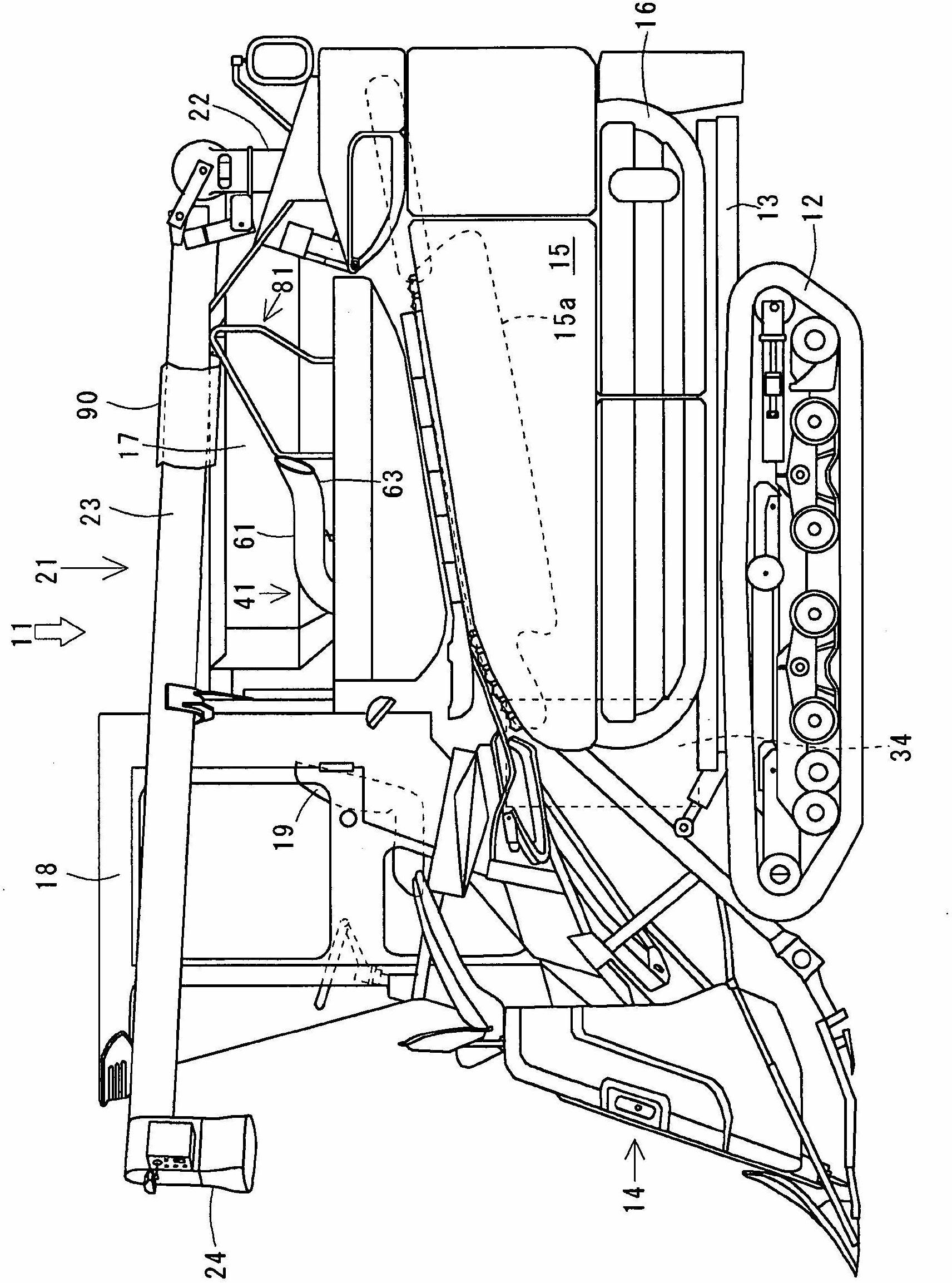
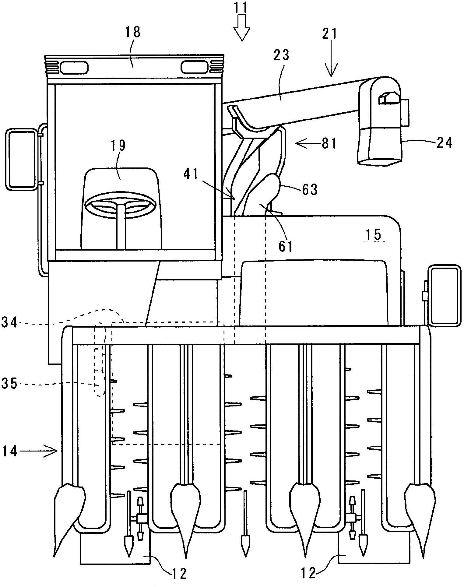
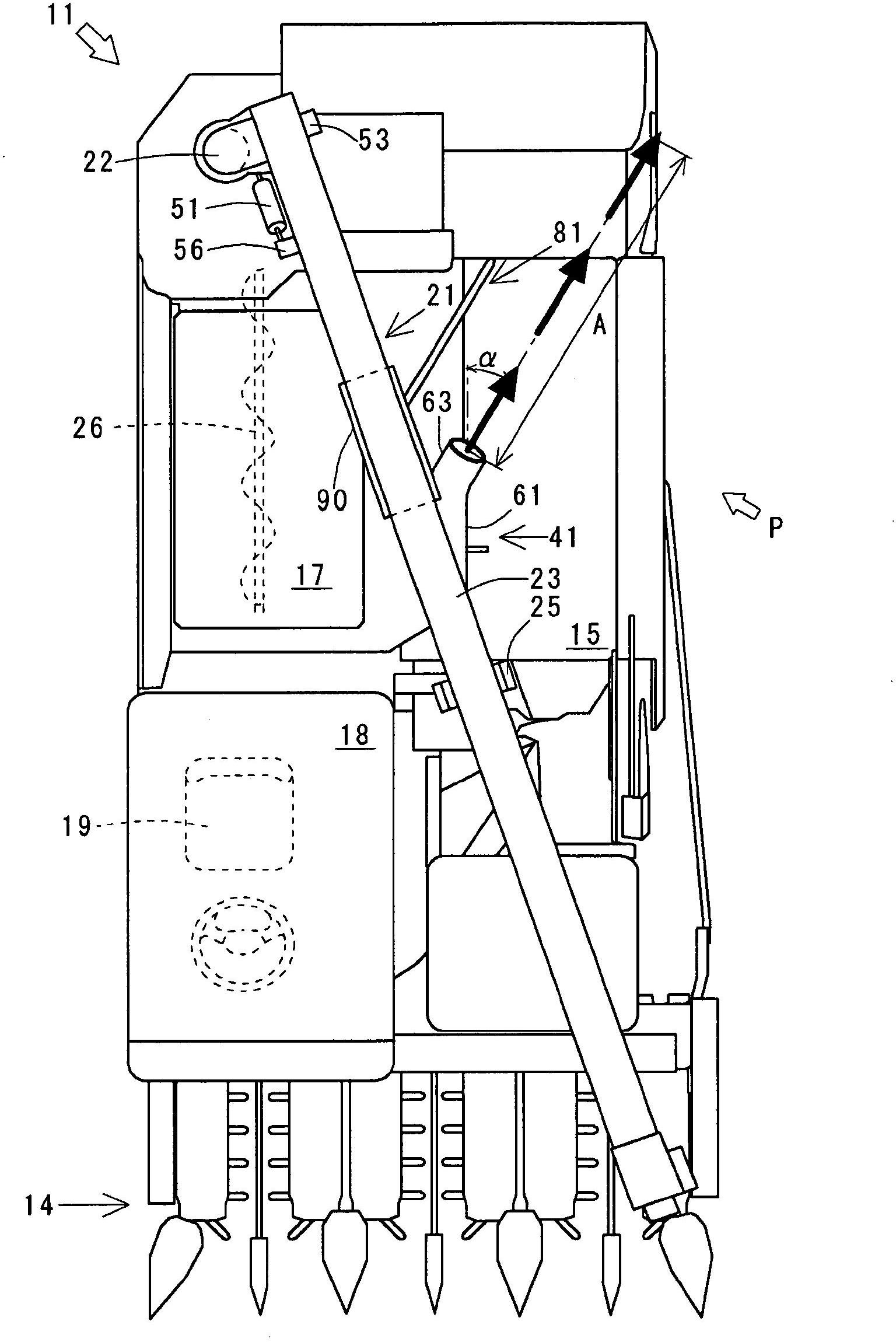
[0055] The combine 11 which concerns on 1st Example of this invention is demonstrated using a figure. figure 1 is an overall side view of the combine harvester 11, figure 2 is the front view of combine harvester 11, image 3 is a top view of the combine harvester 11, Figure 4 is a brief side view of the exhaust device 41, Figure 5 is a schematic front view of the exhaust device 41, Image 6 is a schematic top view of the exhaust device 41, Figure 7 is a schematic side view of the connecting portion of the longitudinal conveying screw 22 and the transverse conveying screw 23, Figure 8 yes image 3 The arrow P of the protective plate 90 in the view, Figure 9 is a side view of the fender 90, Figure 10 is a top view of the protective plate 90, Figure 11 is a cross-sectional view of the fender 90, Figure 12 (a) is a top view of a conventional outside air introduction part 71, (b) is a top view of the outside air introduction part 71 when opening the upstream end p...

Embodiment 2

[0098] A second embodiment of the present invention will be described below using the drawings.

[0099] The combine which concerns on this Example is demonstrated using a figure. Figure 16 is the overall side view of the combine harvester, Figure 17 is the main view of the combine harvester, Figure 18 is a top view of the combine harvester, Figure 19 is a brief side view of the exhaust, Figure 20 is a simplified front view of the exhaust, Figure 21 is a simplified top view of the exhaust.

[0100] First, the overall structure of the combine 111 is demonstrated. Such as Figure 16 to Figure 18 As shown, the combine harvester 111 is equipped with a body (underframe) 113 on a crawler belt traveling device 112 that supports left and right crawlers, and an engine 134 is mounted on the right side of the front part of the body 113 (see Figure 19 ). In front of the machine body 113, a transmission case 131 (refer to Figure 21 ), on the gearbox 131 the axles of the dr...


PUM


Abstract

A combine harvester having an exhaust device capable of efficiently discharging exhaust gas in a direction away from a machine body. The combine harvester has a grain tank (17) for containing hulls after harvesting, threshing, and sorting processes, and also has the exhaust device (41) constructed from a silencer (42), a tail pipe (61), etc., with one end of the exhaust device connected to an engine (34) mounted on the machine body and the other end extended between a threshing section (15) and the grain tank (17). The tail pipe (61) connected to an exhaust manifold (36) of the engine (34) on the upstream side of the exhaust device (41) is supported by support members (82, 83) arranged on the threshing section (15).

Description

[0001] This application is a divisional application of an invention patent application named "Combine Harvester", with an international filing date of August 27, 2007, an international application number of PCT / JP2007 / 066575, and a national application number of 200780035648.0. technical field [0002] The present invention relates to a combine harvester, and more specifically relates to the combine harvester technology in which an exhaust device is arranged on the upper part of the body. Background technique [0003] In the past, the exhaust device of the combine harvester is to pass through the lower part of the body from the engine and is arranged on the side of the body rear, and the exhaust gas produced by the engine is discharged at the body rear. The exhaust device includes an exhaust muffler for reducing exhaust sound, a tailpipe for exhausting exhaust gas, and the like (for example, refer to Patent Document 1). [0004] However, if exhaust devices such as exhaust mu...

Claims


Application Information

Patent Timeline
Patent Type & Authority Applications(China)
IPC IPC(8): A01D41/02A01D41/12F01N13/08
CPCA01D41/12F01N1/00F01N13/08F01N2340/04F01N2590/00
Inventor 正野润一
Owner YANMAR POWER TECHNOLOGY CO LTD
Why Eureka
Try Eureka