Numerical control processing method for corner of groove cavity

A processing method, the technology of turning

Inactive Publication Date: 2012-09-12
XIAN AIRCRAFT IND GROUP
View PDF7 Cites 5 Cited by
  • Summary
  • Abstract
  • Description
  • Claims
  • Application Information

AI Technical Summary

Problems solved by technology

However, when using a tool with a length-to-diameter ratio greater than 5 for five-axis plunge milling, the tool is prone to chatter and damage the corner of the part during machining.

Method used


Image

  • Numerical control processing method for corner of groove cavity
  • Numerical control processing method for corner of groove cavity
  • Numerical control processing method for corner of groove cavity

Examples


Embodiment Construction

[0010] After analyzing the structural features of many products, the processing method of the present invention has advantages for the processing of the corner structure of the cavity, especially for the small absolute value of the corner, the angle between one side of the corner and the bottom surface of the cavity is less than 90 degrees, and the tool is long. When the diameter ratio is greater than 5, it has obvious advantages.

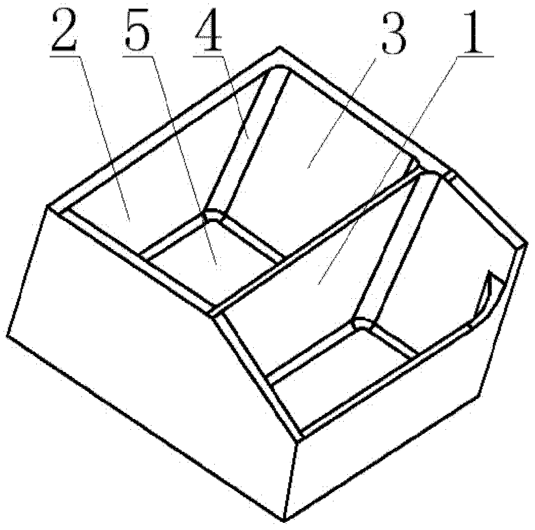
[0011] as attached figure 1 Shown: the body 1 of the box-shaped part to be processed shown in the embodiment is a cavity part with a corner, and the first side 2 of the cavity and the second side 3 of the cavity are not perpendicular to the bottom surface 5 of the cavity (the included angles are respectively 83 degrees and 102.9 degrees); the value of the groove corner 4 is R10.5mm, and the groove depth is 132mm.

[0012] The first step is to carry out rough machining of the cavity according to the bottom surface and side wall of the part with 3mm...


PUM


Abstract

The invention discloses a numerical control processing method for a corner of a groove cavity. The method comprises the following steps: firstly, parts of the groove cavity are processed through allowance removal roughing, and allowance for finish is left on the bottom surface and side walls of the groove cavity; secondly, finish machining is carried out on the bottom surface and the side walls of the groove cavity; and finally, when a corner structure of the groove cavity is processed through finish machining, an obvious included angle is formed between a central shaft of a cutter and an axial line of the corner; and the cutter feeds to cut the corner of the groove cavity in the axis direction of the corner, and the track of the cutter is parallel to the axial line of the corner.

Description

technical field [0001] The invention relates to the technical field of numerical control machining, in particular to a numerical control machining method for the corners of groove cavities in aircraft parts. Background technique [0002] At present, the main load-bearing parts in the aircraft structure are rapidly developing in the direction of large-scale and integrated. The processing cost of such parts is high and the manufacturing cycle is long. In order to effectively reduce the manufacturing risk of parts and save production costs, the manufacturability of such parts has become a new focus in the design process. However, in the actual design process, due to the requirements of aircraft structure assembly and parts riveting, there will usually be a groove corner structure that requires five-axis linkage machining of CNC machine tools to realize, that is, the height is too large relative to the corner radius, and there is at least one side ( Usually on both sides) the s...

Claims


Application Information

Patent Timeline
Patent Type & Authority Applications(China)
IPC IPC(8): B23C3/00
Inventor 王中胜田辉杨龙惠昕张文文
Owner XIAN AIRCRAFT IND GROUP
Why Eureka
Try Eureka