Swirling flow shaft with a plurality of swirling chambers
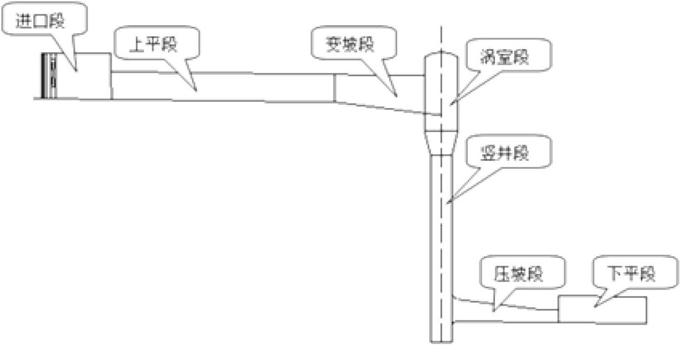
A technology of vortex chambers and shafts, which is applied in water conservancy projects, sea area projects, coastline protection, etc., can solve the problems of expensive project cost, long construction period, and increase the difficulty of water conservancy project hub layout, etc., and achieves convenient and flexible use, strong applicability, The effect of reducing difficulty
- Summary
- Abstract
- Description
- Claims
- Application Information
AI Technical Summary
Problems solved by technology
Method used
Image
Examples
Embodiment 1
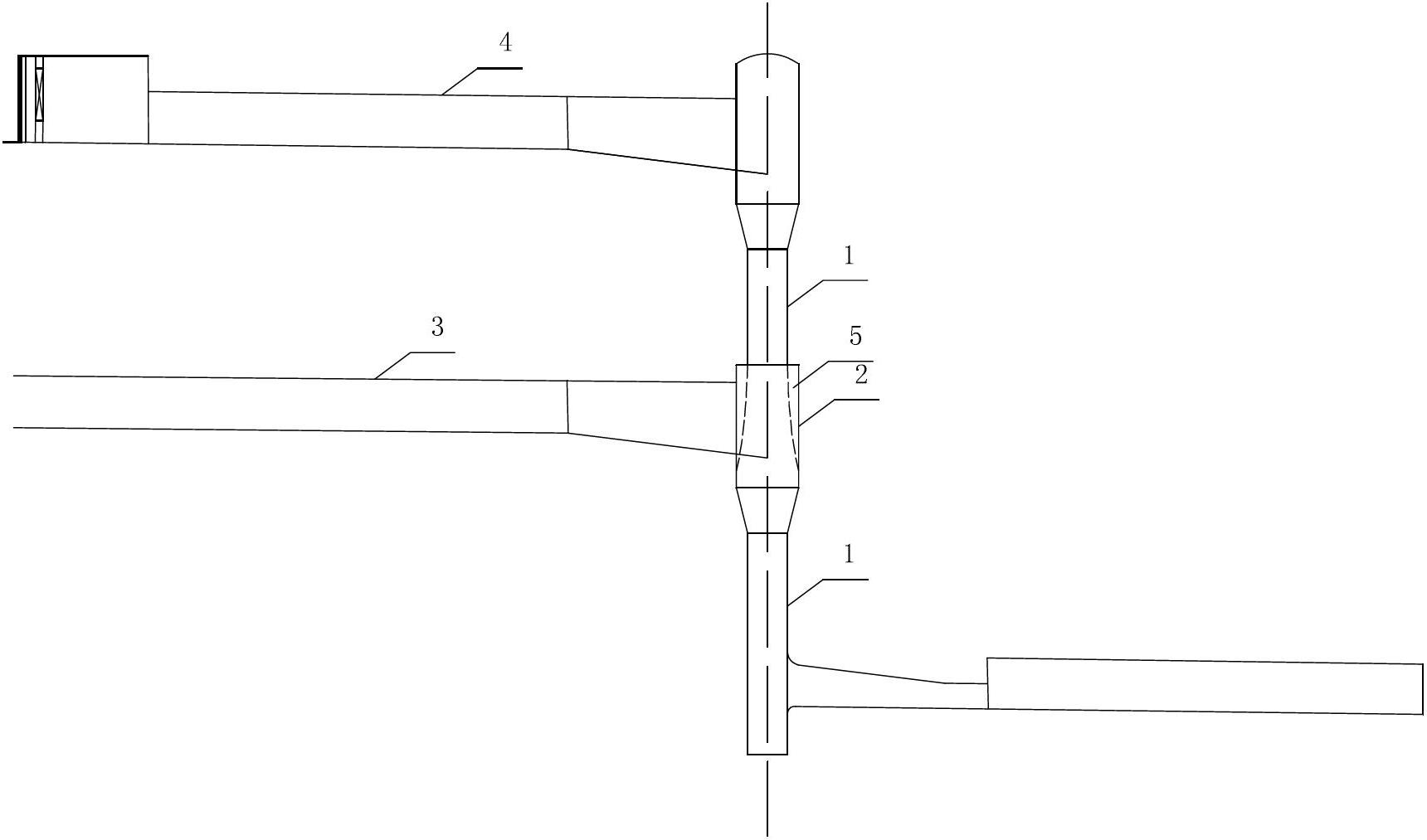
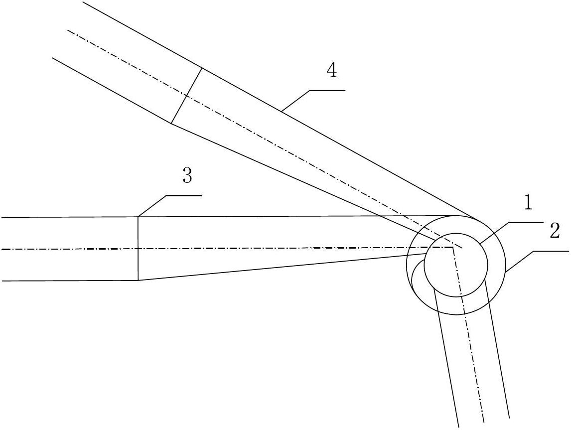
[0022] Such as figure 2 As shown, the swirling shaft given in this embodiment is based on a hydraulic facility composed of a spillway tunnel equipped with a swirling flow energy dissipation of the shaft, and a sudden expansion vortex chamber 2 is coaxially added to the shaft section 1. And the additional whirlpool chamber 2 is connected to the lower spillway tunnel 3, the lower spillway tunnel 3 and the higher spillway tunnel 4 in this embodiment are not on the same plane, and their axis directions are also different ,see image 3 . The diameter of the lower shaft where the vortex chamber 2 is added can be determined to be greater than or equal to the diameter of the upper shaft according to the flow rate of the discharge tunnel 3 at the lower position. In addition, the inlet of the lower discharge tunnel 3 connected to the additional vortex chamber 2 is completely located in the side wall cavity 5 (ie, the dashed line) formed between the downstream flow and the wall of the ad...
Embodiment 2
[0024] Such as Figure 4 As shown, the swirling shaft given in this embodiment is based on a hydraulic facility composed of a spillway tunnel with a swirling energy dissipating shaft, and two sudden expansion shafts are added coaxially on the elevation of the shaft section 1. The vortex chamber 2, and the additional vortex chamber 2 is connected to the lower discharge tunnel 3, the lower discharge tunnel 3 and the higher discharge tunnel 4 may be on the same plane or not on the same plane . The diameter of the lower shaft where the vortex chamber 2 is added can be determined to be greater than or equal to the diameter of the upper shaft according to the flow rate of the discharge tunnel 3 at the lower position. In addition, the inlets of the two lower discharge tunnels 3 respectively connected to the two additional vortex chambers 2 are completely located in the side wall cavity 5 (that is, the dashed line) formed between the downward discharge flow and the wall surface of the...
PUM
 Abstract
Description
Claims
Application Information
 - R&D
- Intellectual Property
- Life Sciences
- Materials
- Tech Scout
- Unparalleled Data Quality
- Higher Quality Content
- 60% Fewer Hallucinations
Browse by: Latest US Patents, China's latest patents, Technical Efficacy Thesaurus, Application Domain, Technology Topic, Popular Technical Reports.
© 2025 PatSnap. All rights reserved.Legal|Privacy policy|Modern Slavery Act Transparency Statement|Sitemap|About US| Contact US: help@patsnap.com


