Coalface straightness control method

A coal mining face and control method technology, applied to mining equipment, earthwork drilling, mine roof support, etc., can solve the problems of lower production efficiency, uneven movement of scraper conveyors, etc., and achieve simple structure, low cost, The effect of high reliability

Active Publication Date: 2012-09-12
BEIJING TIANMA INTELLIGENT CONTROL TECH CO LTD
8 Cites 58 Cited by

AI-Extracted Technical Summary

Problems solved by technology

At present, the working face of the hydraulic support manual system is all manually pushed or pulled to control the straightening of the scraper conveyor. The electro-hydraulic control system of the hydraulic support uses a stroke sensor to control the movement of the hydraulic support. The connecting hole of the conveyor is U-shaped, and there is a large gap between it and...

Method used

Most of the stroke control of the hydraulic support adopts the built-in stroke sensor, because the downhole working face environmental condition is poor, the space is narrow and small, and there is no operating space, therefore, it is difficult to carry out troubleshooting and e...

Abstract

The invention discloses a coalface straightness control method. A range finder and an angle sensor are mounted on the top beam of a hydraulic support, the range finder is used for measuring the distance between the hydraulic support and a coal wall, and the angle sensor is used for detecting the posture of the top beam of the hydraulic support; a support controller is mounted on the hydraulic support and is used for detecting the states of the hydraulic support and controlling the actions of the hydraulic support. The hydraulic support and a scraper conveyer are connected by a pin lug, and the movement of the scraper conveyer is realized through the push-slip control of the hydraulic support. In the moving process of the hydraulic support, the distance between the hydraulic support and the coal wall is detected, and the moving travel of the hydraulic support is controlled at the same time, so the distance between the moved hydraulic support of the coalface and the coal wall remains the same, the control on the straightness of the coalface hydraulic support is realized, the control on the straightness of the scraper conveyer is realized through the push-slip action of the coalface hydraulic support, and the control on the straightness of the whole coalface is accordingly realized.

Application Domain

Mine roof supports

Technology Topic

Control engineering

Image

  • Coalface straightness control method
  • Coalface straightness control method
  • Coalface straightness control method

Examples

  • Experimental program(1)

Example Embodiment

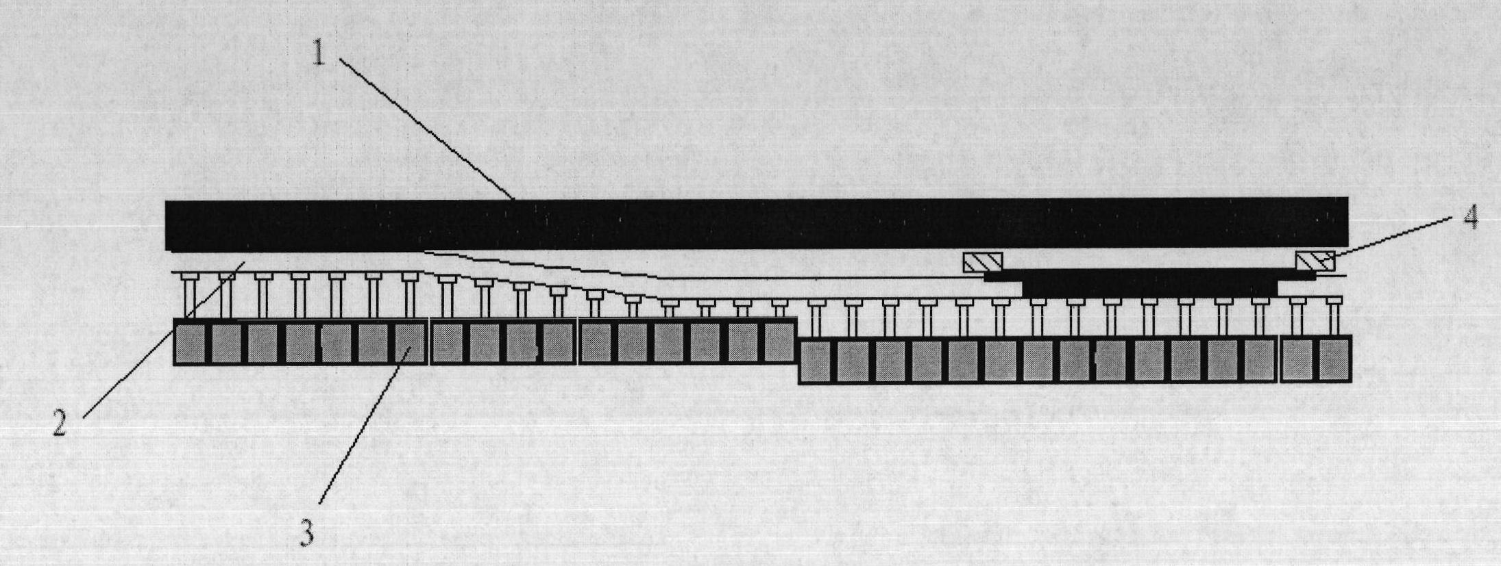
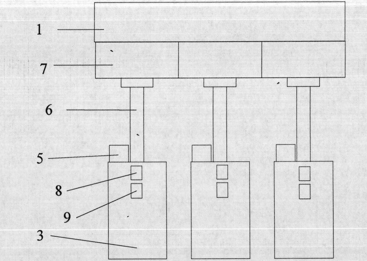
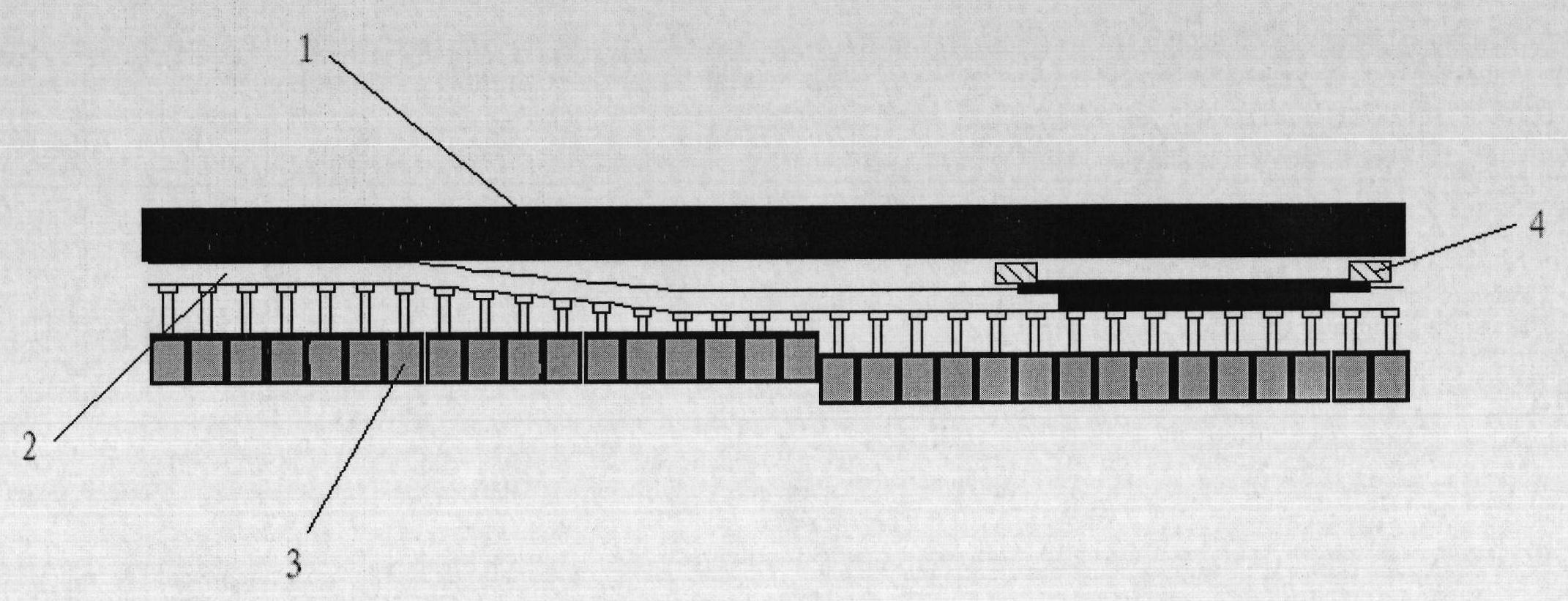
[0020] A preferred embodiment of the method for controlling the straightness of the coal mining face according to the present invention. In the working process, the coal mining face is basically a straight line, so its related equipment should also maintain a certain straightness. The straightness of the coal mining face in the present invention includes the straight lines of multiple hydraulic supports in the working face. And the straightness of its scraper conveyor. In the straightness control method of the coal mining face of the present invention, the straightness control device of the coal mining face includes a hydraulic support, a scraper conveyor, a distance meter, an angle sensor and a support controller. The scraper conveyor is usually arranged close to the coal mining face, and the shearer runs on it. It consists of multiple chutes. A group of multiple hydraulic supports arranged in sequence are provided on one side of the scraper conveyor to support coal mining. The roof of the working face, and with the advancement of the coal mining face, the scraper conveyor is pushed to the coal wall of the coal face through the pushing jack. Each hydraulic support is connected to a chute, thereby connecting the hydraulic support and the scraper conveyor stand up. The rangefinder is installed on the top beam of the hydraulic support to detect the distance between the hydraulic support and the coal wall. The angle sensor is also set on the top beam of the hydraulic support to detect the tilt angle of the top beam of the hydraulic support; on the hydraulic support A support controller is also installed to perform the action control and status detection of the hydraulic support. The steps and methods for the action control and status detection are common knowledge in the field and will not be repeated here. There are usually multiple hydraulic supports in the working face. Preferably, each hydraulic support is provided with a rangefinder, an angular velocity sensor and a support controller, and the support controllers are electrically connected to each other, which can carry out data transmission and communication between each other. Signal exchange.
[0021] Since the moving process of the hydraulic support is also the movement of the hydraulic support relative to the coal wall, and at the same time, since the scraper conveyor is connected with the hydraulic support through the pin lugs, the position of the scraper conveyor also migrates with the movement of the hydraulic support, therefore, effective control The straightness of the hydraulic support during the movement of the entire working face can better control the straightness of the scraper conveyor and ensure the straightness of the scraper conveyor. It is also a prerequisite for ensuring the coal cutting effect of the shearer. The straightness control of the working face creates good conditions, which forms a virtuous circle and can realize the attitude control of the working face. The distance meter is installed on the top beam of the hydraulic support to ensure that there are no obstacles between the distance meter and the coal wall during the process of moving the hydraulic support, so as to ensure that the distance between the distance meter and the coal wall can be effectively measured. The distance, each rangefinder installed on the hydraulic support should be installed facing the coal wall and kept vertical to the coal wall. The position of each rangefinder on the hydraulic support should be the same. Ensure that its posture is relatively straight with the working face bottom plate, and its posture can be obtained by the angular velocity sensor also installed on the top beam, and feedback adjustment by the support controller to ensure that the position of the hydraulic support is perpendicular to the coal wall of the working face. In order to eliminate the influence of the installation position, the positioning error of individual hydraulic supports can be compensated in the corresponding support controller to ensure the measurement accuracy.
[0022] The control method of the hydraulic support is:
[0023] Before the hydraulic support moves, the support controller issues an instruction to measure the distance between the hydraulic support and the coal wall, and saves it. The support controller issues the instruction to move the hydraulic support, and continuously reads the hydraulic pressure during the movement. The distance between the support and the coal wall changes until the given target stroke is reached. In the process of moving the hydraulic support, an angle sensor should be used to detect the attitude of the top beam of the hydraulic support to ensure that the distance meter and the working face bottom plate maintain a horizontal distance to ensure that the distance between the hydraulic support and the coal wall is comparable to the hydraulic pressure. The telescopic length of the moving cylinder is the same.
[0024] The stroke control of the hydraulic support mostly adopts built-in stroke sensor. Due to the poor environmental conditions of the underground working face, the narrow space and no operating space, it is difficult to troubleshoot and replace the equipment when the stroke sensor fails. The top beam of the hydraulic support adopts an external method, which facilitates the maintenance and replacement of the equipment and improves the maintainability of the system.
[0025] The above-mentioned support controller controls and adjusts the straightness of the hydraulic support and the scraper conveyor according to the acquired measurement data of the rangefinder, including:
[0026] ① Before starting the straightening of the working face, first straighten the working face and cut the coal with the shearer, and make the coal wall produced by the shearer cut straight, so as to be the reference standard for the subsequent hydraulic support control;
[0027] ② After the standard coal wall is generated on the working face, the automatic straightening function is activated. During the transfer of the hydraulic support, the movement of the hydraulic support balance jack is controlled by the support controller to make the top beam of the hydraulic support level with the bottom plate;
[0028] ③In the process of moving the hydraulic support, the support controller continuously reads the data of the rangefinder and detects the distance between the hydraulic support and the coal wall (or the change in the distance between the hydraulic support and the coal wall), when the specified value is reached , End the process of moving the hydraulic support.
[0029] ④Each hydraulic support implements the frame transfer process according to the above ①-③, completes the transfer of the entire working face hydraulic support, and realizes the straightness control of the working face hydraulic support.
[0030] ⑤After the hydraulic support is moved, the full stroke push/pull action is performed during the push/pull action. Since the straightness of the hydraulic support is guaranteed, the starting position of this full stroke push/pull action The straightness of the conveyor is also guaranteed. This eliminates the influence of the connecting pin ear error between the scraper conveyor and the hydraulic support during the previous full-stroke push/pull action, and better realizes the straightness of the scraper conveyor on the working surface control.
[0031] The above are only the preferred specific implementations of the patent of the present invention, but the scope of protection of the patent of the present invention is not limited to this. Any person skilled in the art can easily think of it within the technical scope disclosed in the patent of the present invention. The changes or replacements should be covered by the scope of protection of the invention patent.

PUM

no PUM

Description & Claims & Application Information

We can also present the details of the Description, Claims and Application information to help users get a comprehensive understanding of the technical details of the patent, such as background art, summary of invention, brief description of drawings, description of embodiments, and other original content. On the other hand, users can also determine the specific scope of protection of the technology through the list of claims; as well as understand the changes in the life cycle of the technology with the presentation of the patent timeline. Login to view more.

Similar technology patents

Photoelectric sensor for position of sun

InactiveCN101650173AEffective tracking range expandedSimple structure
Owner:WUHAN UNIV OF TECH

Magnetic cooling apparatus and control method thereof

ActiveUS20130180263A1simple structure
Owner:SAMSUNG ELECTRONICS CO LTD

Dual-Drivetrain of Power-Assist Vehicle

InactiveUS20100181130A1enhance uphill momentumsimple structure
Owner:CHOU WEN CHENG

Classification and recommendation of technical efficacy words

  • Simple structure
  • low cost

System and method for transmitting wireless digital service signals via power transmission lines

ActiveUS7929940B1reduce bandwidth requirementlow cost
Owner:NEXTEL COMMUNICATIONS

Plastic waveguide-fed horn antenna

InactiveUS20100214185A1low cost
Owner:RGT UNIV OF CALIFORNIA

System and method for determination of position

InactiveUS20090149202A1low costreduce requirement
Owner:STEELE CHRISTIAN

Adaptive antenna optimization network

InactiveUS6961368B2low costminimal space
Owner:ERICSSON INC
Why Eureka
Try Eureka