
Transmission device capable of converting straight line movement into rotating movement

A technology of rotary motion and transmission device, which is applied in the direction of transmission device, belt/chain/gear, mechanical equipment, etc., can solve the problems of large wear between motion pairs, difficult crank and connecting rod mechanism, and inability to achieve fixed-angle rotation, etc. The effect of high transmission efficiency, simple structure and low energy consumption

Inactive Publication Date: 2014-09-17
伍尚强
View PDF5 Cites 0 Cited by
  • Summary
  • Abstract
  • Description
  • Claims
  • Application Information

AI Technical Summary

Problems solved by technology

However, the piston reciprocates once, and the crankshaft (crank) rotates a circle, which cannot achieve a fixed angle of rotation.
Therefore, the crank-link mechanism is not easy to accurately realize complex movements, and the design of the crank-link mechanism is relatively complicated, and the wear between the kinematic pairs is relatively large

Method used


Image

  • Transmission device capable of converting straight line movement into rotating movement
  • Transmission device capable of converting straight line movement into rotating movement
  • Transmission device capable of converting straight line movement into rotating movement

Examples


Embodiment Construction

[0020] The present invention will be further described below in conjunction with the accompanying drawings and specific embodiments.

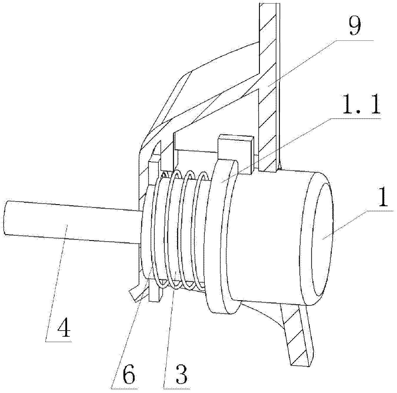
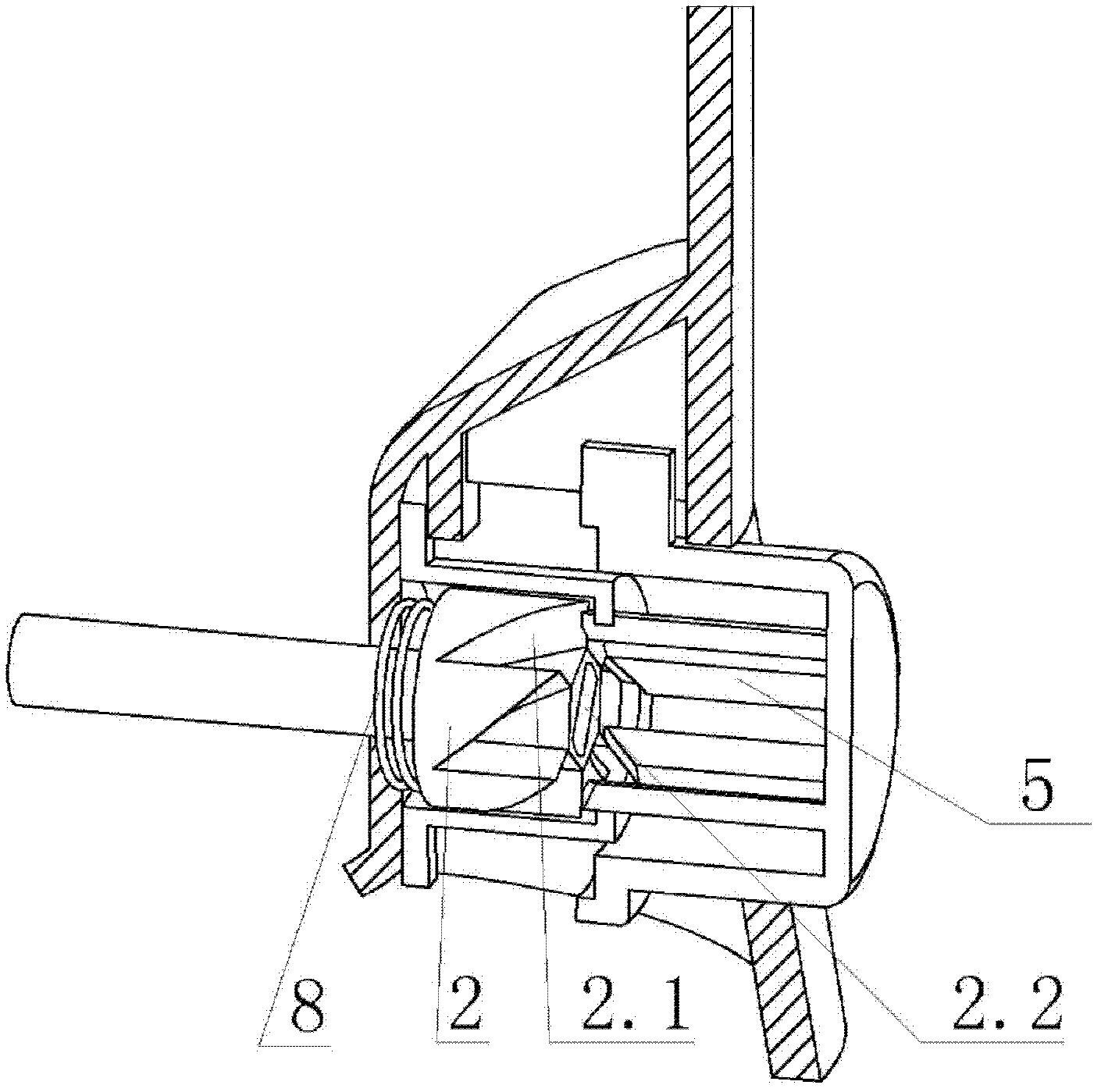
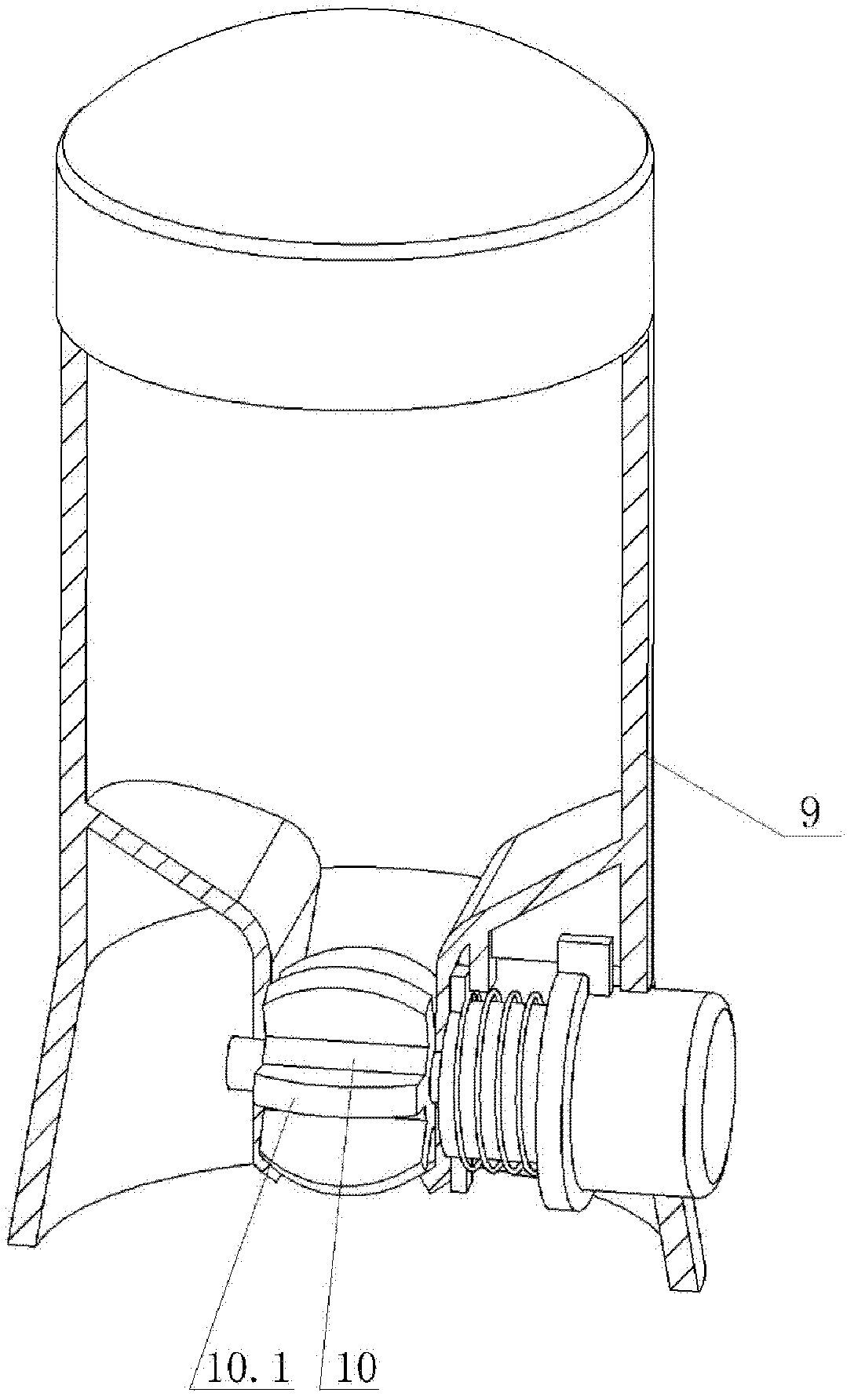
[0021] Such as Figure 1 to Figure 8 As shown, the transmission device for converting linear motion into rotary motion of the present invention includes a push cover 1 for reciprocating linear motion, a rotating core 2 for converting reciprocating linear motion into rotary motion, a rotating sleeve 3, and a rotating shaft 4 for outputting rotary motion .

[0022] The push cover 1 has two or more first extruding blocks 5 with first extruding surfaces 5.1 at the ends of two or more evenly distributed circumferentially. In this embodiment, the number of first extruding blocks 5 is six. The push cover 1 also has a spring 6 for returning. The revolving sleeve 3 is set on the rotating core 2, and the revolving sleeve 2 has a number of second extruding blocks 7 uniformly distributed in its circumferential direction equal to that of the first extrudi...


PUM


Abstract

The invention provides a transmission device capable of converting straight line movement into rotating movement. The transmission device comprises a push cover for performing reciprocating straight line movement, a rotating core and a continuously rotating sleeve for converting the reciprocating straight line movement into rotating movement, and a rotating shaft for outputting the rotating movement; the push cover is provided with two or more than two first squeezing blocks, the squeezing blocks are arranged uniformly around the push cover and the upper end parts of the first squeezing blocks are provided with first squeezing surfaces; the push cover is provided with a spring for resetting; the continuously rotating sleeve is sleeved on the rotating core; the continuously rotating sleeve is sleeved with second squeezing blocks, the number of the second squeezing blocks is equal to that of the first squeezing blocks, the second squeezing blocks are arranged uniformly around the continuously rotating sleeve and the end parts of the second squeezing blocks are provided with second squeezing surfaces; the rotating core is provided with an inclined squeezing surface which is matched with the first squeezing surfaces of the first squeezing blocks and the second squeezing surfaces of the second squeezing blocks; the rotating core is provided with an axial reset spring for axially resetting; and the end part of the rotating shaft is axially and movably arranged in a circumferential limit hole at the output end of the rotating core and synchronously rotates with the rotating core. With the adoption of the transmission device provided by the invention, the reciprocating straight line movement can be converted into directed rotating movement; and meanwhile, a certain angle is rotated once the transmission device performs reciprocating straight line movement.

Description

Technical field: [0001] The invention relates to a transmission device, in particular to a transmission device for converting linear motion into rotary motion. Background technique: [0002] The meshing transmission through a spur rack and a gear is a relatively common transmission device that converts linear motion into rotary motion. This transmission device usually makes the push rod into a straight rack and the rotor into a gear. Through the meshing of the rack and the gear, the linear motion of the push rod is converted into the rotary motion of the rotor, but the rotation direction of the rotor changes with the reciprocation of the push rod, and cannot form the same rotation. [0003] In addition, the crank-link mechanism can convert linear reciprocating motion into directional rotary motion, such as an internal combustion engine, which converts heat energy generated during fuel combustion into mechanical energy of piston reciprocating motion, and then converts it into...

Claims


Application Information

Patent Timeline
Patent Type & Authority Patents(China)
IPC IPC(8): F16H27/02
Inventor 伍尚强
Owner 伍尚强
Learn More