Three-axis linkage contour error compensation control method for cylinder cam machining

A contour error, cylindrical cam technology, applied in the direction of program control, computer control, general control system, etc., can solve the distance contour error of tangent line, the difficulty of description and calculation and compensation, the calculation method of contour error, the lack of research on compensation method and other problems , to achieve the effect of high calculation accuracy and simple calculation method

Inactive Publication Date: 2012-09-12
SHANDONG UNIV OF TECH
View PDF5 Cites 12 Cited by
  • Summary
  • Abstract
  • Description
  • Claims
  • Application Information

AI Technical Summary

Problems solved by technology

In the case of linear axis linkage, the description of contour error is intuitive and easy to calculate and compensate; but in the case of linear axis and rotary axis linkage, the description of contour error and calculation compensation are more difficult
[0003] A search of existing technical literature found that the existing research results mostly focus on the contour error coupling control method when two or three linear axes are linked, but there are few calculation methods and compensation methods for the contour error when the linear axis and the rotary axis are linked. have research
For example, in the paper "Analysis and Design of Integrated Control for Multi-Axis Motion Systems" published in the academic journal "IEEE TRANSACTIONS ON CONTROL SYSTEMS TECHNOLOGY" (2003, 11(3): 375-382), Syh-Shiuh Yeh proposed When the three linear axes are linked, the distance from the actual tool position point in a certain sampling period to the tangent line at the current interpolation point on the command tool path curve is approximated as the contour error; Liu Yi et al. ): 3381-3386) in the paper "Optimal Contour Control and Simulation Based on Working Coordinate System", it is proposed to establish the Frenet coordinate system on the desired trajectory as the working coordinate system when the three linear axes are linked, and use the position to follow the The normal component of the error in the working coordinate system is used to approximate the contour error; Gong Shihua et al. published a paper on the academic journal "Electrical Automation" (2010, 32(4): 11-13) "Camshaft Grinding Contour Error In "Adaptive Control", aiming at the simultaneous machining of a linear axis and a rotary axis, an expression for the contour error of camshaft grinding in the polar coordinate system is proposed, but the description of the contour error model is relatively abstract

Method used


Image

  • Three-axis linkage contour error compensation control method for cylinder cam machining
  • Three-axis linkage contour error compensation control method for cylinder cam machining
  • Three-axis linkage contour error compensation control method for cylinder cam machining

Examples


Embodiment Construction

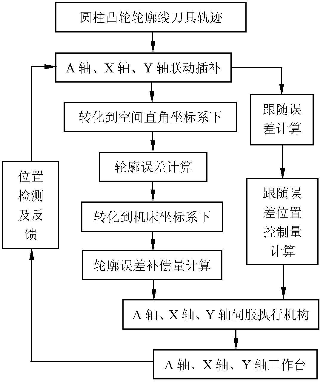
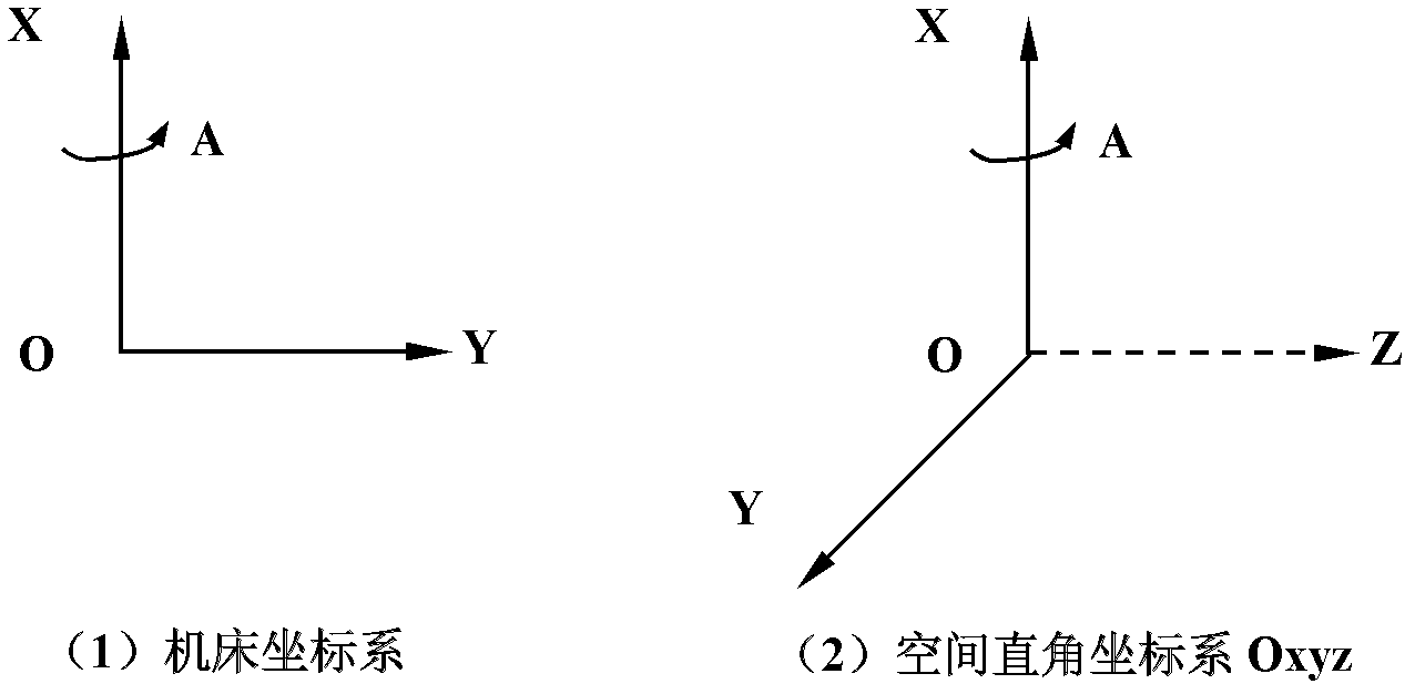
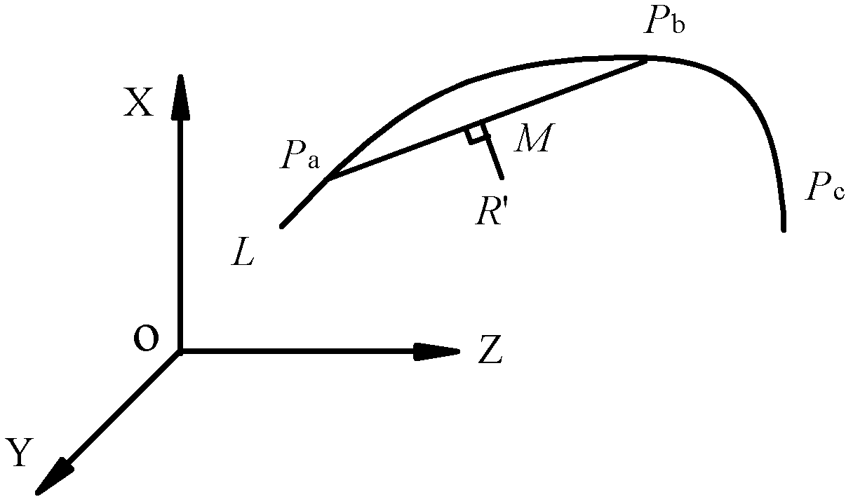
[0020] For the simultaneous machining of cylindrical cams with A-axis, X-axis, and Y-axis, the following combination Figure 1~4 The present invention is described in further detail:

[0021] 1) if figure 2 As shown, when using the A-axis, X-axis, and Y-axis to process the cylindrical cam, the X linear axis is perpendicular to the Y linear axis, and the A axis is the rotation axis around the X axis, so as to establish the machine tool coordinate system; the established space Cartesian coordinates In the Oxyz system, in addition to the X linear axis and Y linear axis of simultaneous machining, the Z linear axis is also virtualized, and the X axis, Y axis, and Z axis conform to the right-handed Cartesian coordinate system.

[0022] In each sampling period of the interpolation processing of the tool track of the cylindrical cam contour line, in the machine tool coordinate system, the current work of each axis is detected by the respective position sensors (such as circular grat...


PUM


Abstract

The invention relates to a three-axis linkage contour error compensation control method for cylinder cam machining. The method carries out contour error calculation and compensation during an interpolation machining process according to the linkage of axis A, axis X and axis Y, and is characterized in that the method comprises the steps of in each sampling cycle detecting the actual location of the worktable of axis A, axis X and axis Y in a machine tool coordinate system; converting into a space rectangular coordinate system and approximating the distance between the actual cutter location point and the line connecting with the two closest interpolation points on the tool path of the cylindrical cam contour at contour errors; converting into the machine tool coordinate system to obtain the corresponding contour errors of axis A, axis X and axis Y; and introducing a scaling factor, acquiring the contour error compensation quantities through proportional control, separately stacking the contour error compensation quantities with the location control quantities of shaft A, shaft X and shaft Y to follow errors, and outputting to a servo actuator. The method provided by the invention has the advantages that during axis A, axis X and axis Y linkage machining contour error description is intuitive, calculation precision is high, and contour error compensation method is simple and effective.

Description

technical field [0001] The invention relates to a contour error compensation control method, in particular to a three-axis linkage contour error compensation control method for cylindrical cam machining. Background technique [0002] Compared with the planar cam mechanism, the cylindrical cam mechanism has small volume, compact structure, good rigidity, reliable operation, and large transmission torque. It has great advantages in realizing gap indexing motion and large motion lift. Cylindrical cams belong to space cams, and can be divided into linear follower cylindrical cams and oscillating follower cylindrical cams according to the movement mode of the follower. A CNC milling machine with a rotary table can be used to process the cylindrical cam profile. For example, on a vertical CNC milling machine with a rotary table, the X feed axis and the A rotary axis can be used to process the cylindrical cam of the linear follower. Use the X feed axis, Y feed axis, and A rotation...

Claims


Application Information

Patent Timeline
Patent Type & Authority Applications(China)
IPC IPC(8): G05B19/404
Inventor 赵国勇赵玉刚王士军赵庆志
Owner SHANDONG UNIV OF TECH
Why Eureka
Try Eureka