
An electronic device based on MEMS technology

A technology of electronic equipment and technology, applied in the field of electronic equipment based on MEMS technology, can solve the problem of not conforming to the original intention of generalized instruction design, and achieve the effect of enhancing personalized experience and improving compatibility

Inactive Publication Date: 2012-09-12
AU OPTRONICS CORP
View PDF0 Cites 3 Cited by
  • Summary
  • Abstract
  • Description
  • Claims
  • Application Information

AI Technical Summary

Problems solved by technology

[0003] However, when forming the above-mentioned control commands, mechanical, touch and somatosensory commands must use body movements, and the body movements or signals reflecting the body movements often require a series of complex operations on the control panel of the electronic device. operation, it is not intuitive to execute application functions through these types of control commands
In addition, voice-activated or voice-based instructions need to make sounds, and only support some languages, which have high requirements on the user's language ability, which does not meet the original design intention of generalized instructions

Method used


Image

  • An electronic device based on MEMS technology
  • An electronic device based on MEMS technology

Examples


Embodiment Construction

[0018] In order to make the technical content disclosed in this application more detailed and complete, reference may be made to the drawings and the following various specific embodiments of the present invention, and the same symbols in the drawings represent the same or similar components. However, those skilled in the art should understand that the examples provided below are not intended to limit the scope of the present invention. In addition, the drawings are only for schematic illustration and are not drawn according to their original scale.

[0019] As mentioned above, in existing electronic devices, body movements are required to form mechanical commands, touch commands, and somatosensory commands, and the body movements or signals reflecting the body movements often need to be controlled by the electronic device. A series of complex operations are performed on the panel, and application functions cannot be executed intuitively through these types of control commands...


PUM


Abstract

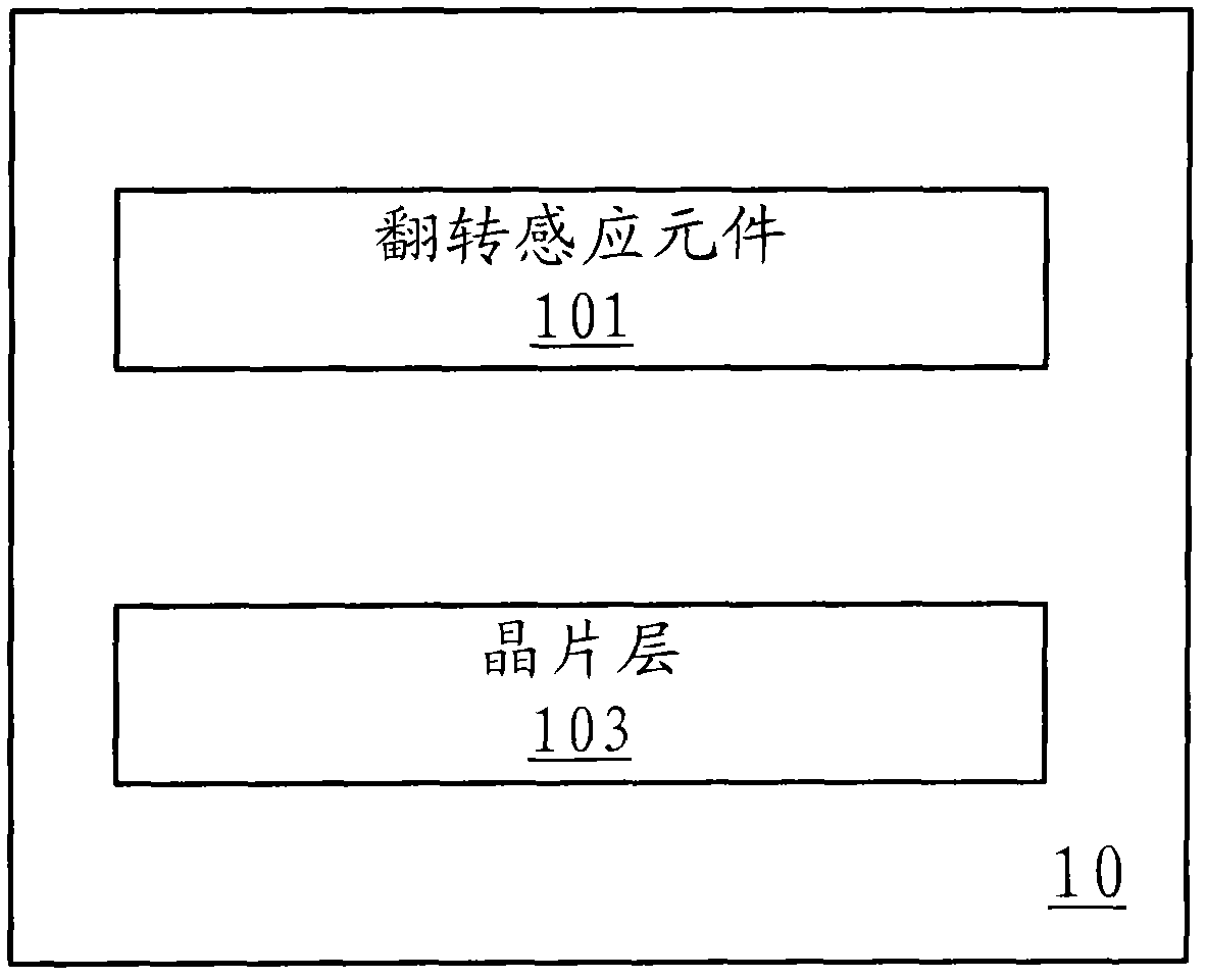
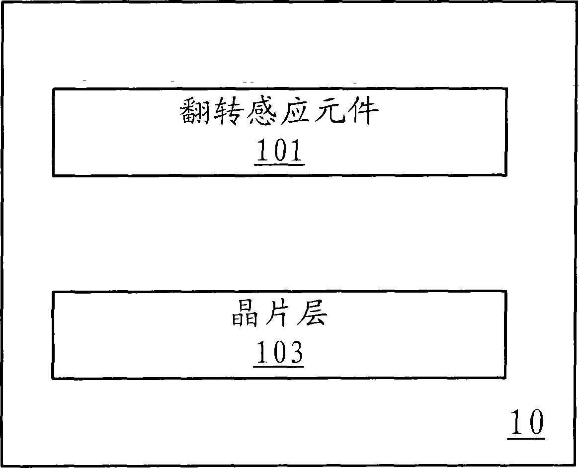
The invention provides an electronic device based on MEMS technology, comprising a rollover sensor which comprises: a rollover sensing element for detecting rollover angle of the electronic device and outputting a corresponding electric induction signal; and a wafer layer connected with the rollover sensing element for outputting a control signal corresponding to the electric induction signal. The rollover sensing element of the rollover sensor is used for detecting the rollover angle of the electronic device and outputting the corresponding electric induction signal, and the wager layer is used for receiving the electric induction signal for outputting the corresponding control signal. Compared with the prior art, users can operate the electronic device without carrying out a series of complex operations on the control panel, the corresponding control signal is formed through an intuitionistic rollover instruction to enable and disable or switch an application function, and accordingly the electronic device compatibility is improved and the user customized experience is enhanced.

Description

technical field [0001] The present invention relates to electronic equipment, in particular to an electronic equipment based on MEMS (Micro Electromechanical System, Micro Electromechanical System) technology. Background technique [0002] At present, with the development of science and technology and the substantial improvement of research and development capabilities, the functional design of some digital products is becoming more and more humanized. For example, in these digital products, users can control electronic devices to realize corresponding functions through mechanical button commands, touch commands, somatosensory commands and voice commands. Specifically, the mechanical button command triggers the corresponding touch button through the downward pressure of the finger, and then turns on or off the application function of the button; the touch command touches the resistive film or the capacitive film through the finger to make it correspond to The pixel voltage ...

Claims


Application Information

Patent Timeline
Patent Type & Authority Applications(China)
IPC IPC(8): G06F3/033H04M1/725G06F3/0346
Inventor 宋昀静郑崇孚林岳锋蔡伟翔陈一绫
Owner AU OPTRONICS CORP
Learn More