Energy storage capacitor-based cascaded inverter circuit

A technology of energy storage capacitors and cascaded inverters, which is applied to electrical components, output power conversion devices, and conversion of AC power input to DC power output. problem, achieve the effect of reducing quantity, improving power quality and improving efficiency

Inactive Publication Date: 2012-09-12
SHANGHAI MARITIME UNIVERSITY
View PDF3 Cites 15 Cited by
  • Summary
  • Abstract
  • Description
  • Claims
  • Application Information

AI Technical Summary

Problems solved by technology

This kind of transformer is bulky, costly and difficult to design
On the other hand, due to its structural limitations, it is difficult to achieve four-quadrant operation

Method used


Image

  • Energy storage capacitor-based cascaded inverter circuit
  • Energy storage capacitor-based cascaded inverter circuit
  • Energy storage capacitor-based cascaded inverter circuit

Examples


Embodiment Construction

[0022] In order to make the technical means, creative features, goals and effects achieved by the present invention easy to understand, the present invention will be further described below in conjunction with specific embodiments.

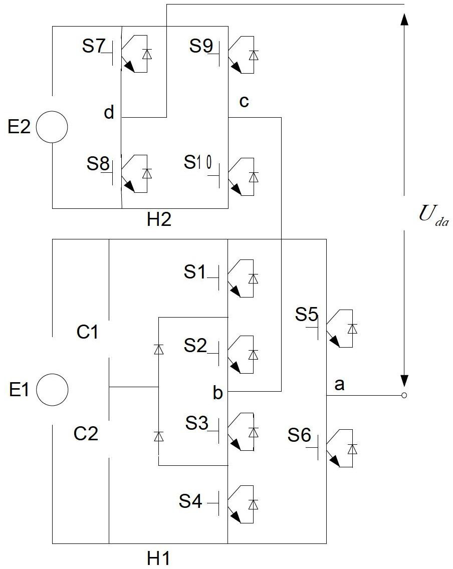
[0023] Currently existing hybrid cascade circuits such as figure 1 As shown, the circuit is obtained by cascading two bridge circuits. One is an H-bridge circuit and the other is an asymmetrical three-level H-bridge circuit. This circuit has a minimum number of components, does not require a large number of clamping diodes and flying capacitors, and is more suitable for grid interfacing, but requires multiple DC voltage sources.

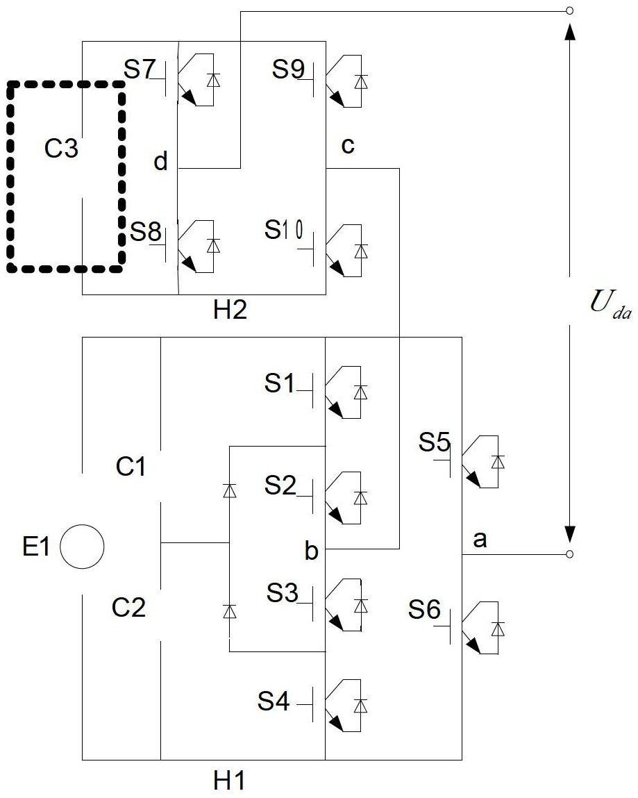
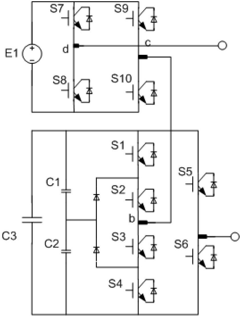
[0024] The structure of the single-phase hybrid cascaded inverter circuit proposed by the present invention is as follows: figure 2 As shown, the H1 bridge is an asymmetrical 3H bridge inverter with a DC source, and the H2 bridge is a 2H bridge inverter without a DC source but with a capacitor C3, where C3 is an energ...


PUM


Abstract

The invention discloses an energy storage capacitor-based cascaded inverter circuit. The energy storage capacitor-based cascaded inverter circuit consists of an asymmetrical three-level circuit and an H bridge circuit, which are cascaded, wherein the voltage output points of the asymmetrical three-level and the H bridge circuit are modulated through a switching device, and then are connected. The energy storage capacitor-based cascaded inverter circuit is characterized in that the asymmetrical three-level circuit is connected with a direct current power supply; the H bridge circuit is connected with an energy storage capacitor; and the output of the inverter circuit is the superposition of the output of the two cascaded circuits, and multi-level output can be realized by different modulation methods. Therefore, in a certain operating mode, a flying capacitor can transfer a part of electric energy of the direct current power supply into the energy storage capacitor for storage; and when a load is in a reactive state, electric energy absorbed by the direct current power supply is partially or totally transferred into the energy storage capacitor for storage.

Description

technical field [0001] The invention relates to the field of cascaded inverter circuits, in particular to a cascaded inverter circuit based on energy storage capacitors. Background technique [0002] Due to the characteristics of small output waveform distortion, small dv / dt and small EMI of the system, multi-level converters have become a hot topic in current research, and are more and more widely used in high-power motor drives and AC-DC power transmission. However, the current multilevel converters have various disadvantages, especially when the number of output levels increases, the system topology and control complexity increase significantly, and for the flying capacitor multilevel converter, there is still a problem of unbalanced capacitor voltage. These problems will greatly reduce the reliability of the system. [0003] Compared with the diode box type and flying capacitor type multilevel converter, the cascaded topology has the advantages of requiring the least nu...

Claims


Application Information

Patent Timeline
Patent Type & Authority Applications(China)
IPC IPC(8): H02M7/521
Inventor 韩金刚王光希汤天浩
Owner SHANGHAI MARITIME UNIVERSITY
Why Eureka
Try Eureka