Ophthalmosurgical measuring device

A technology for ophthalmic surgery and measuring devices, applied in the field of ophthalmic surgery systems, can solve the problems of expensive design, high cost of control components, etc.

Active Publication Date: 2012-09-12
CARL ZEISS MEDITEC AG
View PDF6 Cites 3 Cited by
  • Summary
  • Abstract
  • Description
  • Claims
  • Application Information

AI Technical Summary

Problems solved by technology

However, such a solution has the disadvantage that, on the one hand, two pressure sensors would have to be employed, which would result in a very expensive design, and, on the other hand, the signals from the two pressure sensors, which inevitably differ in time constant, would have to be evaluated. processing, which will result in relatively high costs in terms of control elements

Method used


Image

  • Ophthalmosurgical measuring device
  • Ophthalmosurgical measuring device
  • Ophthalmosurgical measuring device

Examples


Embodiment Construction

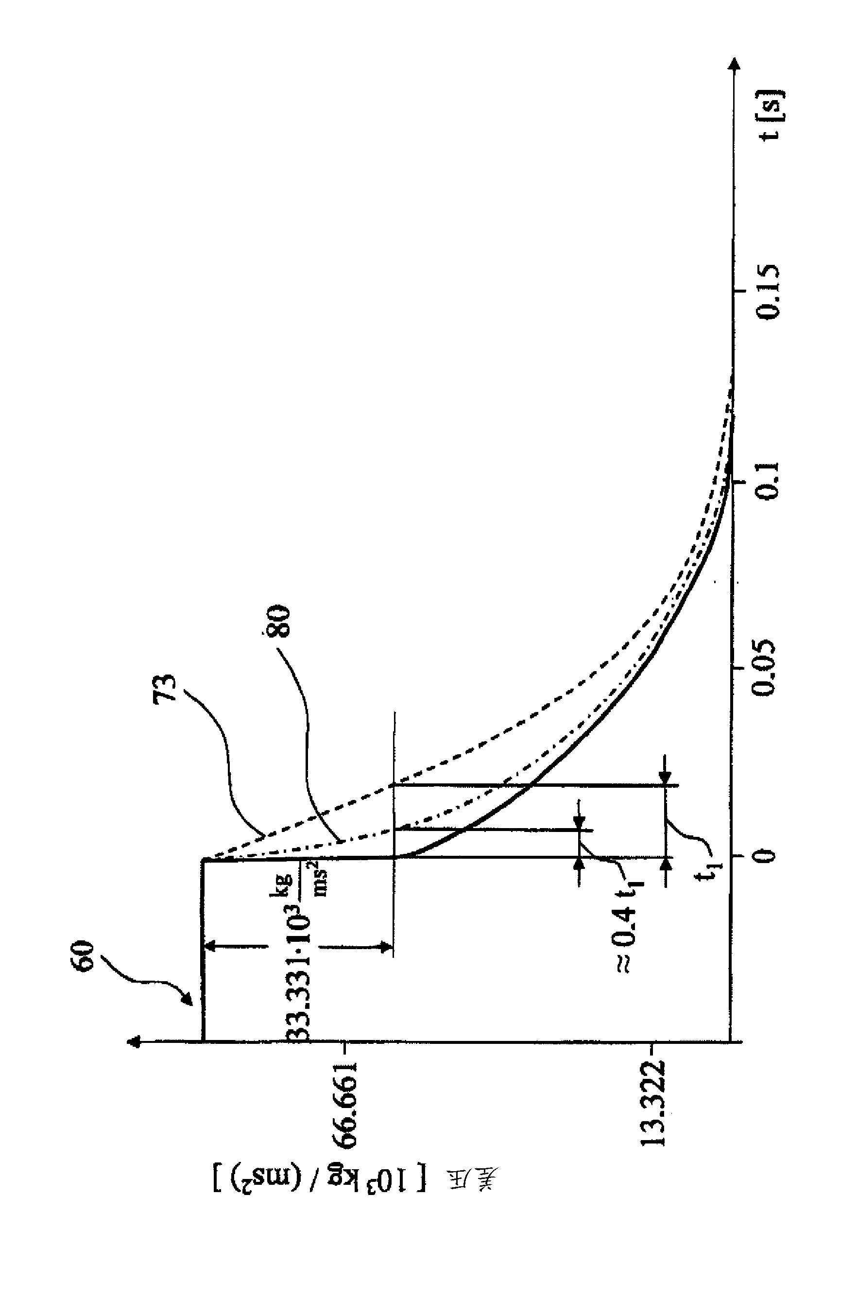
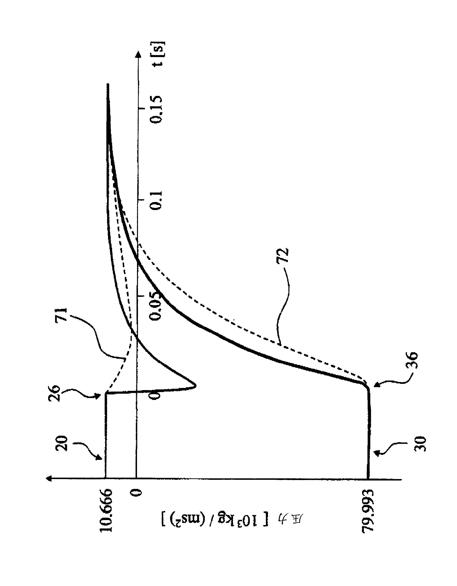
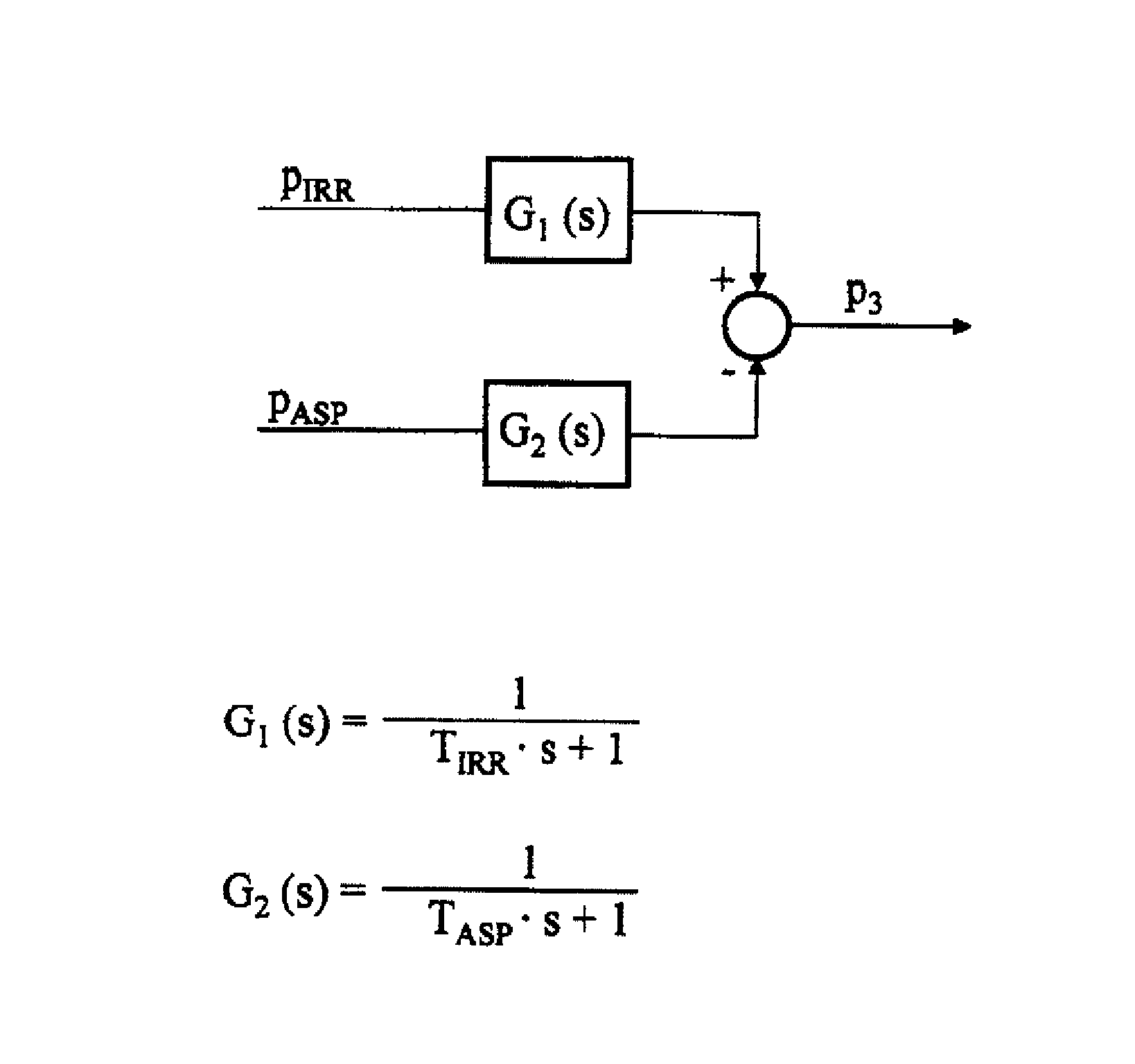
[0025] figure 1 Is a schematic representation of an embodiment of the ophthalmic surgery system 1 according to the present invention. The flushing fluid container 2 contains flushing fluid 3 which can flow through the flushing line 4 to the handpiece 5 having the tip 6. The tip 6 is designed such that it can break the cloudy and relatively hard lens of the eye into small fragments with the aid of a needle that starts to vibrate by ultrasound. The fluid and the broken particles located in the anterior chamber of the eye are guided to the suction pump 8 through the suction line 7, and the suction pump 8 discharges the fluid and particles into the container 9. The sensor 10 is arranged between the flushing line 4 and the suction line 7. In this embodiment, the sensor is connected to the flushing line 4 through the first line 11 and to the suction line 7 through the second line 12. Therefore, it is possible for the sensor to detect the differential pressure between the flushing l...


PUM


Abstract

The invention relates to an ophthalmosurgical measuring device (100) having: an irrigation line (4) through which irrigation fluid (3) can be transported, an aspiration line (7) through which aspiration fluid can be transported to a suction pump (8), and a sensor (10) with which a differential pressure between irrigation line (4) and aspiration line (7) can be detected.

Description

Technical field [0001] The present invention relates to an ophthalmic surgery measuring device, an ophthalmic surgery system having such a measuring device, and a method for operating such a measuring device. Background technique [0002] There are several ophthalmic surgical techniques used to treat the cloudy lens of the human eye. The most widely used technique is phacoemulsification, in which a small tip is introduced into the diseased lens and ultrasonic vibration is used to excite the small tip. In the immediate environment of the vibrating tip, the vibrating tip emulsifies the lens in such a way that the generated lens fragments can be sucked out by the pump via the pipeline. After the lens is completely emulsified, a new intraocular lens can be inserted into the empty capsular bag, so that patients treated in this way can regain good visual acuity. [0003] In phacoemulsification, the device used generally has a vibrating tip in the handpiece, an irrigation line (irrigati...

Claims


Application Information

Patent Timeline
Patent Type & Authority Applications(China)
IPC IPC(8): A61F9/007A61B3/16
CPCA61B2017/00119A61F9/00745A61M5/16854A61M2005/16872A61M2205/332A61M2210/0612A61M3/0216
Inventor C.屈布勒M.艾希勒T.迈尔
Owner CARL ZEISS MEDITEC AG
Why Eureka
Try Eureka