System, method and apparatus for spring-energized dynamic sealing assembly

一种密封组件、弹性体的技术,应用在发动机的密封、发动机元件、活塞环等方向

Inactive Publication Date: 2012-09-12
SAINT GOBAIN PERFORMANCE PLASTICS CORP
View PDF10 Cites 11 Cited by
  • Summary
  • Abstract
  • Description
  • Claims
  • Application Information

AI Technical Summary

Problems solved by technology

While known solutions are effective for some applications, an improved linear dynamic seal is still desired

Method used


Image

  • System, method and apparatus for spring-energized dynamic sealing assembly
  • System, method and apparatus for spring-energized dynamic sealing assembly
  • System, method and apparatus for spring-energized dynamic sealing assembly

Examples


Embodiment Construction

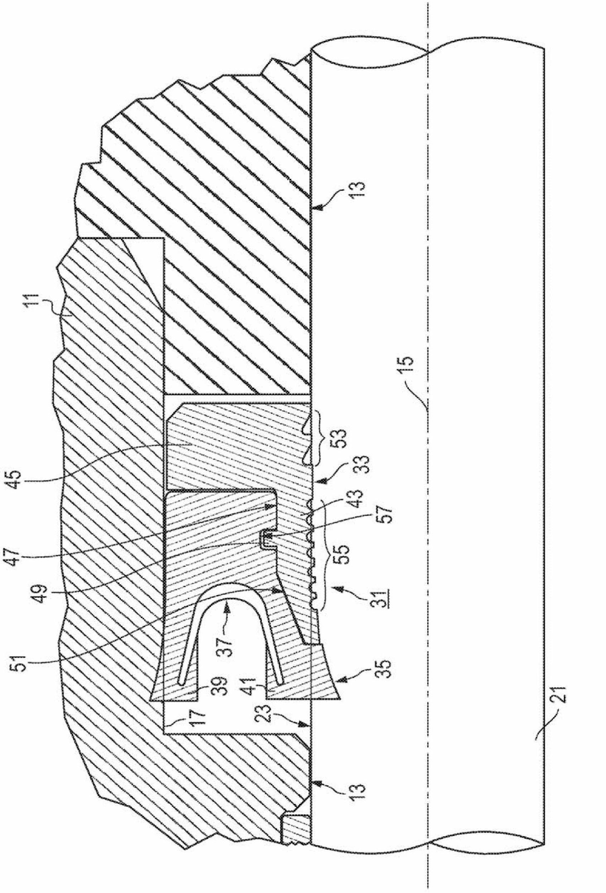
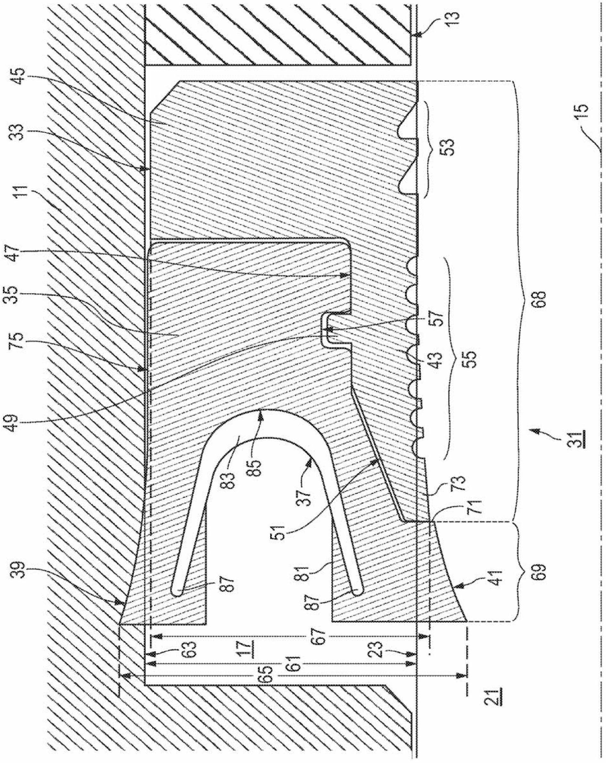
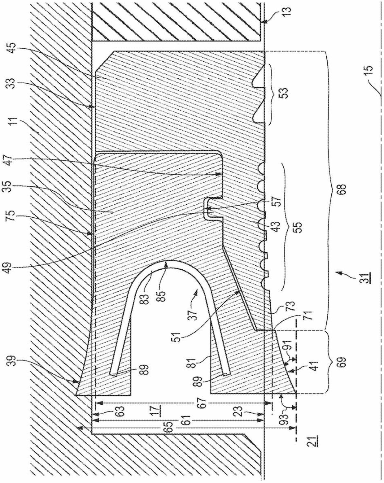
[0015] see Figure 1-7 , disclosing various embodiments of an improved system, method and apparatus for dynamic sealing assemblies, such as for linear motion applications. E.g, figure 1 and 2 An embodiment of a system is disclosed comprising a housing 11 having a bore 13 with an axis 15 and a gland or recess 17 within the bore 13 . A rod 21 is coaxially located in bore 13 for axial movement relative to housing 11 . In the illustrated embodiment, the rod 21 has an outer surface 23 that includes a dynamic surface relative to the bore 13, which has a static surface 63 ( figure 2 ).

[0016] In some embodiments, a seal assembly 31 comprising a radial seal (eg Figure 1-3 and 6) are located in the recess 17 of the hole 13. Seal assembly 31 forms a seal between the housing 11 and rod 21 . In some forms, the seal assembly 31 includes three annular components: a polymeric ring 33, an elastomeric body 35 attached to the polymeric ring 33, and a spring mounted within the elastom...


PUM


Abstract

A seal assembly is disclosed. The seal comprises a metal spring bonded to an elastomer body that is coupled to a polymer ring. The spring may comprise a cantilevered, overlapped metal strip. The elastomer and polymer mechanically interlock with radial members. The elastomer has contacting surfaces configured in outward extending radii to enhance forward edge loading and oil removal from the dynamic surface. In hydraulic service, the seal prevents the egress of hydraulic fluid and ingress of foreign particles.

Description

technical field [0001] The present invention relates generally to seals, and in particular to an improved system, method and apparatus for spring energized elastomeric body and polymer dynamic seal assemblies. Background technique [0002] Dynamic seals for linear motion rods or cylinders used in hydraulic service prevent the loss of hydraulic fluid from the system and the intrusion of foreign particles between moving components. These dynamic or relatively moving surfaces may be located on the inner or outer diameter of the joint. Conventional seals typically include elastomeric bodies that wear quickly or tear easily, or polymers that are more durable but have lower sealing capabilities than elastomeric bodies. [0003] Conventional seals also typically have straight, tapered contact surfaces that limit front side edge loading of the seal and oil removal from the dynamic surface. Furthermore, reverse shaft motion at such seals is reduced due to shear or pumping of viscou...

Claims


Application Information

Patent Timeline
Patent Type & Authority Applications(China)
IPC IPC(8): F16J15/24F16J15/32F16J15/36
CPCF16J15/3216F16J15/322F16J15/3236F16J15/24F16J15/32F16J15/36F16J15/3208F16J15/3252F16J9/06
Inventor M·J·勒恩哈特
Owner SAINT GOBAIN PERFORMANCE PLASTICS CORP
Why Eureka
Try Eureka