
Permanent-magnet synchronous motor

A permanent magnet and synchronous motor technology, applied to synchronous motors with stationary armatures and rotating magnets, magnetic circuit shape/style/structure, magnetic circuit, etc., can solve problems such as torque ripple and induced voltage distortion

Active Publication Date: 2014-09-17
MITSUBISHI ELECTRIC CORP
View PDF5 Cites 0 Cited by
  • Summary
  • Abstract
  • Description
  • Claims
  • Application Information

AI Technical Summary

Problems solved by technology

However, in this case, torque ripple at power-on becomes a problem
[0003] This torque ripple is caused by the distortion of the induced voltage

Method used


Image

  • Permanent-magnet synchronous motor
  • Permanent-magnet synchronous motor
  • Permanent-magnet synchronous motor

Examples


Embodiment approach 1

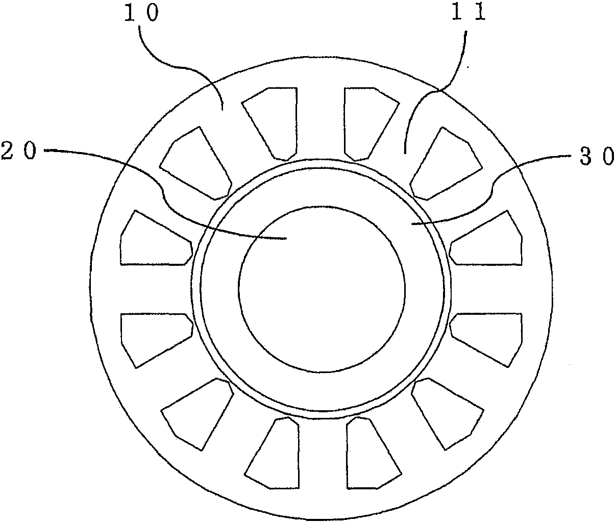
[0032] figure 1It is a sectional view showing a section perpendicular to the axial direction of the permanent magnet synchronous motor in Embodiment 1 of the present invention, and illustrates a motor with 10 poles and 12 slots in the case of Z=12 and 2P=10. Therefore, the value of Z / (3(phase)×2P) corresponds to 12 / (3×10)=2 / 5. figure 1 The permanent magnet synchronous motor of the present invention includes a stator core 10 , a rotor core 20 , and a radially anisotropic ring magnet 30 , and the stator core 10 has a plurality of tooth portions 11 .

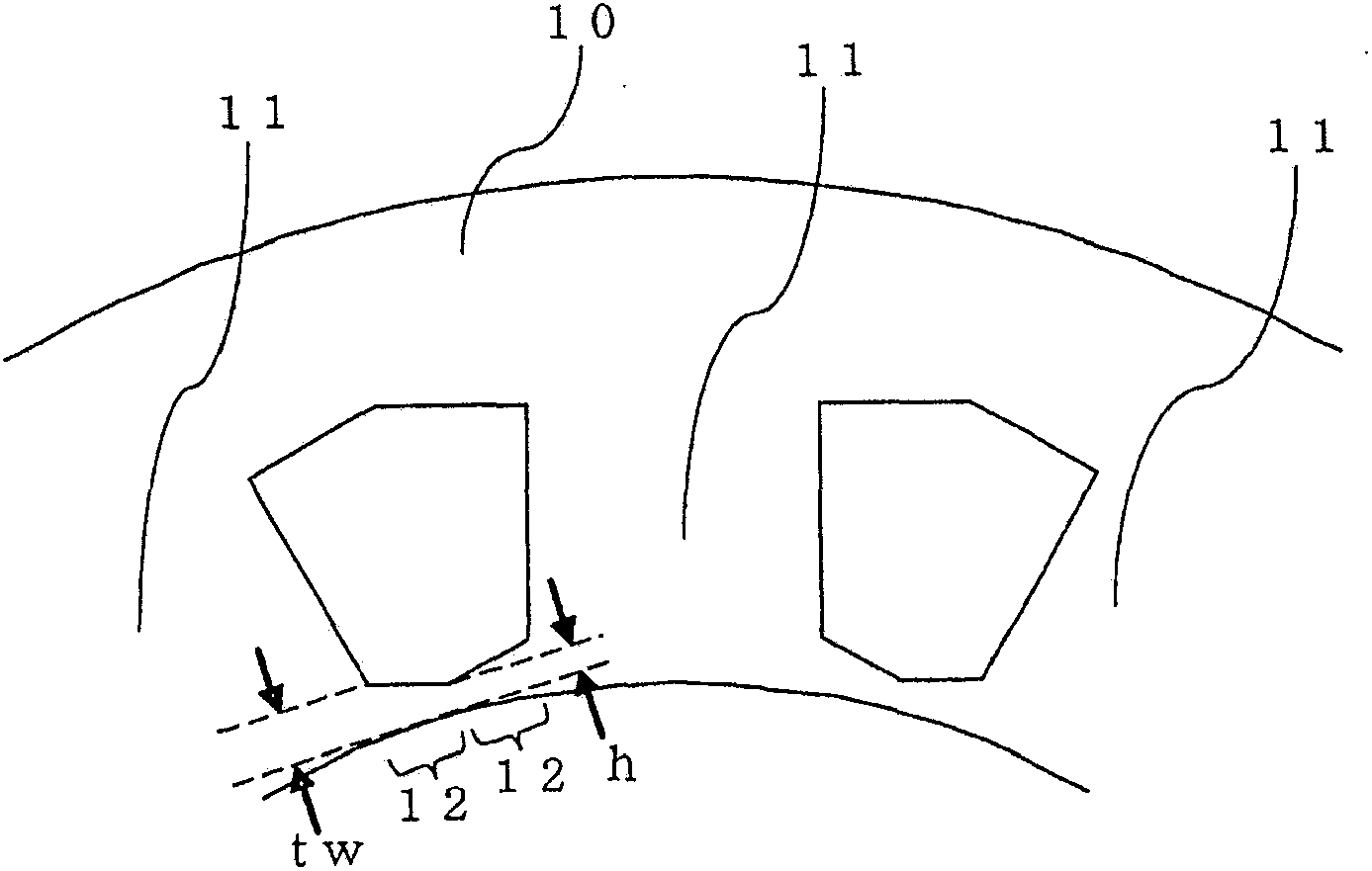
[0033] figure 2 is an enlarged view of the stator core 10 of the permanent magnet synchronous motor in Embodiment 1 of the present invention, and figure 1 The enlarged view of the tooth portion 11 is equivalent. exist figure 1 In the shown 10-pole 12-slot motor, such as figure 2 As shown, there is no gap (so-called slot opening) between adjacent tooth portions 11 . In addition, each tooth portion 11 has a flange portion 12 ...

Embodiment approach 2

[0055] In Embodiment 1 above, a case was described in which a radially anisotropic ring magnet is used in a motor having a small diameter without a gap portion (so-called slot opening) between adjacent tooth portions 11 . On the other hand, in the second embodiment, a case in which a radially anisotropic ring magnet is used in a small-diameter motor having a gap portion (so-called slot opening portion 13 ) between adjacent tooth portions 11 will be described. Condition.

[0056] Figure 7 It is a sectional view showing a section perpendicular to the axial direction of the permanent magnet synchronous motor in Embodiment 2 of the present invention, and illustrates a motor with 10 poles and 12 slots when Z=12 and 2P=10. Therefore, the value of Z / (3(phase)×2P) corresponds to 12 / (3×10)=2 / 5. Figure 7 The permanent magnet synchronous motor of the present invention includes a stator core 10 , a rotor core 20 , and a radially anisotropic ring magnet 30 , and the stator core 10 has ...


PUM


Abstract

Provided is a permanent-magnet synchronous motor whereby a 12f component of torque ripple can be minimized when using a radial anisotropic ring magnet in a small-diameter motor. Said synchronous motor has Z annular stators with wire windings and a permanent magnet with 2P poles, Z / (3·2P) being either 2 / 5 or 2 / 7 (3 being the number of phases). If a radial anisotropic ring magnet is used as the permanent magnet, a 12f component of torque ripple can be minimized by magnetizing the radial anisotropic ring magnet such that the ratio of a flat region to a transition region in the magnetization waveform of one magnetic pole has an appropriate value given tw / h, where h is the tip width of flange parts constituting the tip sections of the stators and tw is the base width of said flange parts.

Description

technical field [0001] The invention relates to a permanent magnet synchronous motor for controlling torque ripple. Background technique [0002] In a permanent magnet type synchronous motor in which one coil is intensively wound on each tooth, the cogging torque at the time of non-energization can be significantly reduced when a combination of the number of poles and the number of slots is appropriately selected. However, in this case, torque ripple at the time of energization becomes a problem. [0003] This torque ripple is caused by distortion of the induced voltage. Therefore, in order to reduce the harmonics of the induced voltage, the shape of the magnet and the like have been devised to make the gap magnetic flux density distribution more sinusoidal. In addition, a technique has been proposed in which a magnet is divided to vary the magnetic flux density of the magnet and to make the gap magnetic flux density distribution close to a sinusoidal wave (for example, re...

Claims


Application Information

Patent Timeline
Patent Type & Authority Patents(China)
IPC IPC(8): H02K1/27H02K15/03H02K21/16
CPCH02K1/2733H02K29/03
Inventor 田中敏则山口信一
Owner MITSUBISHI ELECTRIC CORP
Learn More