Electromotor driving device and compressor driving device
A driving device and motor technology, applied in the control of electromechanical transmission, motor generator control, AC motor control, etc., can solve the problems of reducing input current, narrowing the operating range, etc., and achieve the effect of reducing high-order harmonic components
- Summary
- Abstract
- Description
- Claims
- Application Information
AI Technical Summary
Problems solved by technology
Method used
Image
Examples
Embodiment approach 1
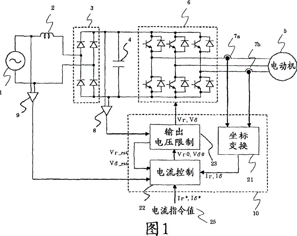
[0057] figure 1 It is a circuit block diagram of the motor drive device according to Embodiment 1 of the present invention.
[0058] exist figure 1 Among them, 1 is a single-phase AC power supply, 2 is a coil, 3 is a rectifier unit, 4 is a smoothing capacitor, 5 is a motor, 6 is an inverter main circuit part, 7a and 7b are phase current detectors, and 8 is a DC voltage detection Unit 9 is a power phase detector and 10 is a control unit.
[0059]The coil 2 is connected between the single-phase AC power source 1 and the rectification unit 3 .
[0060] The rectifying unit 3 rectifies the AC voltage from the single-phase AC power supply 1 into a DC voltage.
[0061] The smoothing capacitor 4 is connected to the output side of the rectification unit 3 to smooth the voltage rectified by the rectification unit 3 .
[0062] The motor 5 is connected to the output side of the inverter main circuit unit 6 and becomes a drive target of the motor drive device according to the first emb...
Embodiment approach 2
[0165] Figure 7 It is a circuit block diagram of the motor drive device according to Embodiment 2 of the present invention.
[0166] exist Figure 7 Among them, the control unit 10 has a current command generation unit 26 .
[0167] The current command generating unit 26 receives the speed command, the magnetic flux command, the output of the coordinate conversion unit 21, the output of the output voltage limiting unit 23, and the output of the power supply phase detector 9, and outputs a current command value 25 (Ir * , Iδ * ).
[0168] The other configurations are the same as those in Embodiment 1, so the same symbols are assigned and descriptions thereof are omitted.
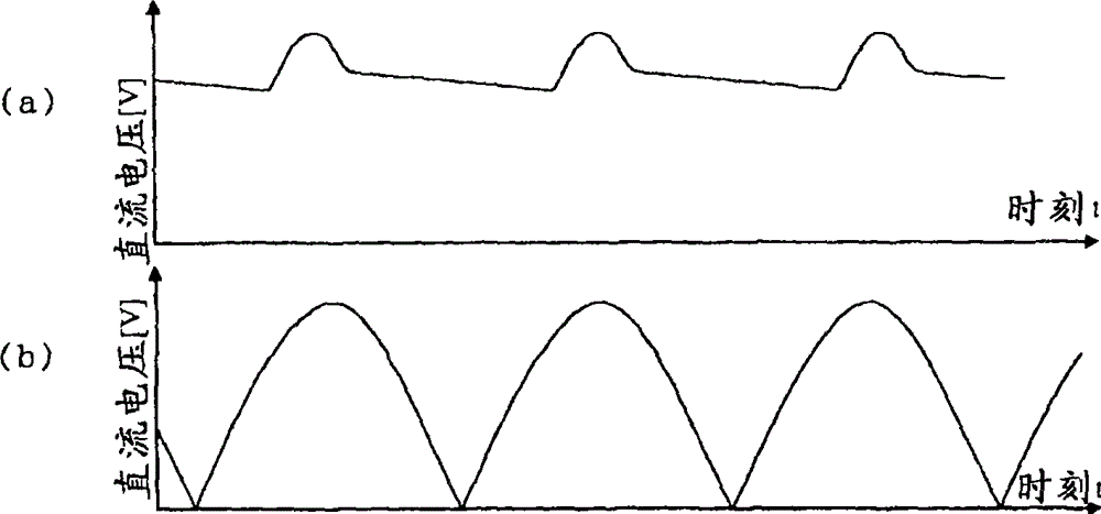
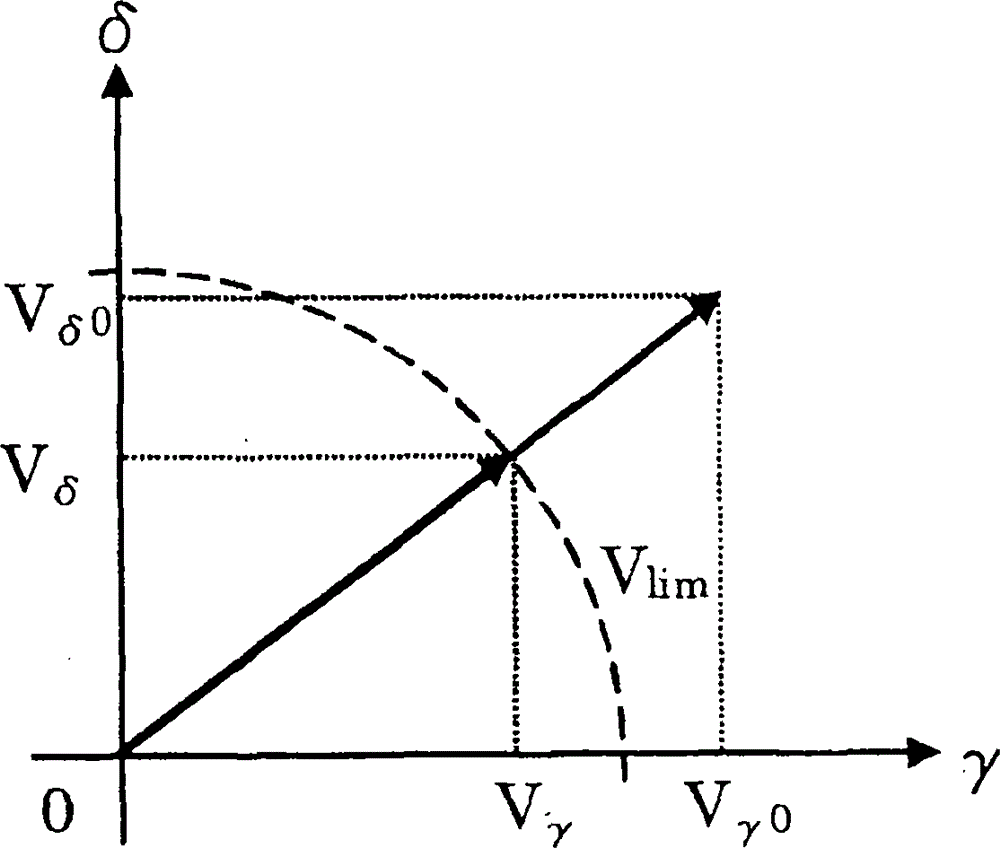
[0169] Also in the second embodiment, as in the first embodiment, since the DC voltage applied to the inverter main circuit unit 6 drops due to ripples, it is sometimes necessary to limit the voltage applied to the motor 5 .
[0170] As a technique corresponding to this situation, there is a technique o...
Embodiment approach 3
[0256] Figure 14 It is a circuit block diagram of a motor drive device according to Embodiment 3 of the present invention.
[0257] exist Figure 14 Among them, the control unit 10 has a position estimation unit 27 .
[0258] The position estimating unit 27 receives the output of the coordinate conversion unit 21 and the output of the output voltage limiting unit 23 , and estimates the energization phase and the rotational speed of the motor 5 .
[0259] The other configurations are the same as those in Embodiment 2, so the same symbols are used to omit description.
[0260] Here, a general problem in estimating the energization phase and the rotational speed of the electric motor 5 will be described first, and then the specific operation of the position estimating means 27 in the third embodiment will be described.
[0261] For example, when the electric motor 5 is a permanent magnet motor, during variable speed operation, the torque is controlled by passing current throu...
PUM
 Abstract
Description
Claims
Application Information
 - R&D
- Intellectual Property
- Life Sciences
- Materials
- Tech Scout
- Unparalleled Data Quality
- Higher Quality Content
- 60% Fewer Hallucinations
Browse by: Latest US Patents, China's latest patents, Technical Efficacy Thesaurus, Application Domain, Technology Topic, Popular Technical Reports.
© 2025 PatSnap. All rights reserved.Legal|Privacy policy|Modern Slavery Act Transparency Statement|Sitemap|About US| Contact US: help@patsnap.com


