Harmonic Elimination Radial Magnetic Circuit Multipole Resolver and Signal Winding Winding Method

A rotary transformer and radial magnetic circuit technology, applied in the direction of transformers, magnetic circuit rotating parts, transformer/inductor parts, etc., can solve the problems of increased volume, low precision, limited application fields, etc., and achieve simple processing. , Improve the measurement accuracy, the effect of a wide range of applications

Active Publication Date: 2016-06-15
HARBIN INST OF TECH
View PDF5 Cites 0 Cited by
  • Summary
  • Abstract
  • Description
  • Claims
  • Application Information

AI Technical Summary

Problems solved by technology

[0003] The purpose of the present invention is to provide a harmonic elimination type radial magnetic circuit multi-pole rotary transformer and a signal winding method to solve the problem that the existing radial reluctance rotary transformer has low precision and its volume decreases with the increase of the number of pole pairs. increase, the problem of limited application field

Method used


Image

  • Harmonic Elimination Radial Magnetic Circuit Multipole Resolver and Signal Winding Winding Method
  • Harmonic Elimination Radial Magnetic Circuit Multipole Resolver and Signal Winding Winding Method
  • Harmonic Elimination Radial Magnetic Circuit Multipole Resolver and Signal Winding Winding Method

Examples


specific Embodiment approach 1

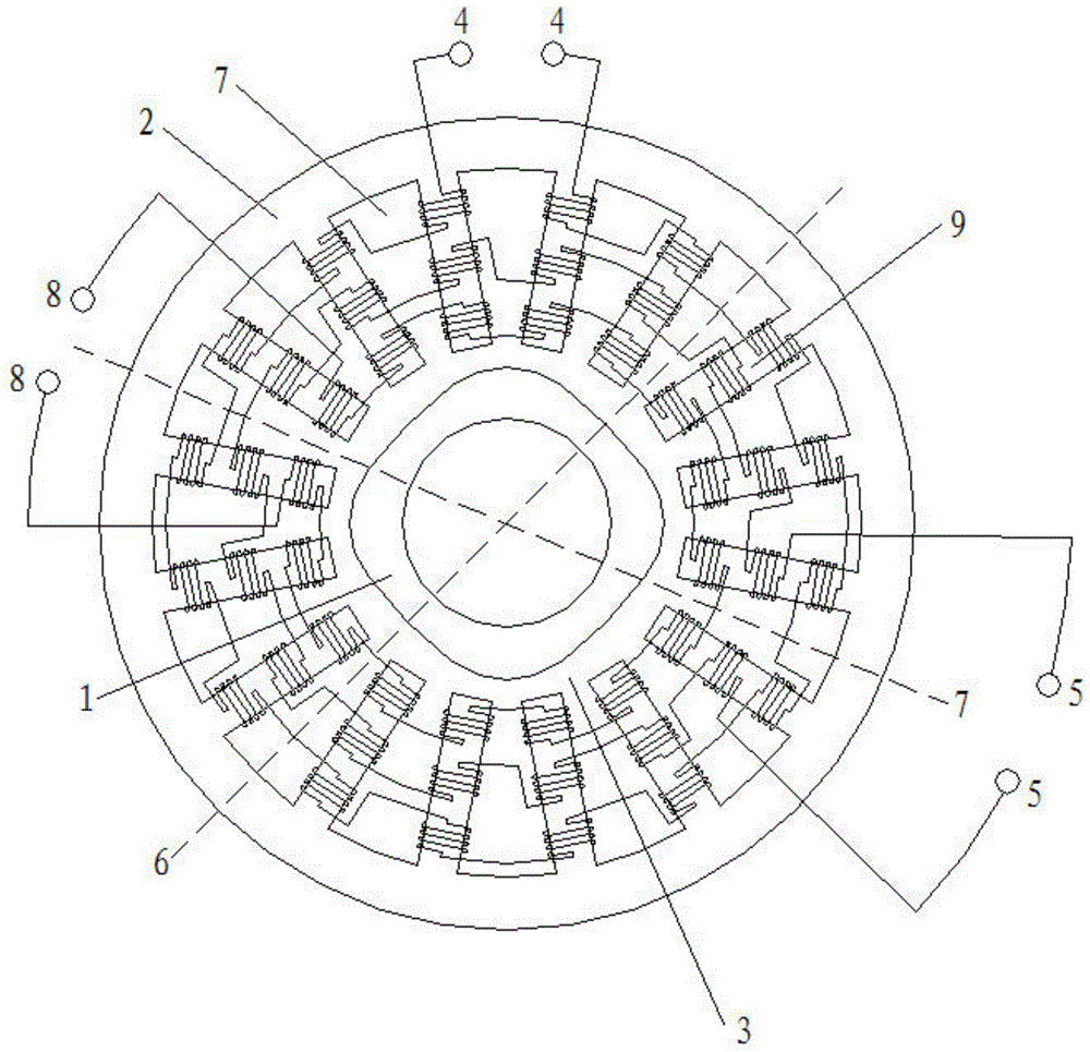
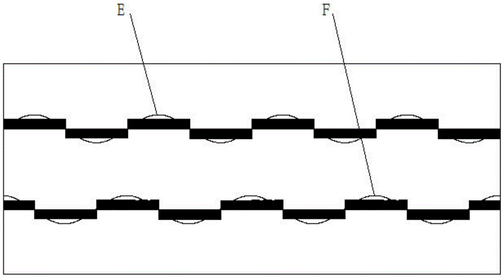
[0017] Specific implementation mode one: as figure 1 , figure 2 As shown, the multi-pole rotary transformer with harmonic elimination radial magnetic circuit includes stator 2, rotor 1, excitation winding 8, sine signal winding 4 and cosine signal winding 5; stator 2 is cylindrical; the connection between stator 2 and rotor 1 There are unequal air gaps 3 between them. The inner surface of the stator 2 is machined with 4NP stator slots 7 and 4NP stator teeth 9 along the axial direction. The 4NP stator slots 7 are evenly distributed along the inner surface of the stator 2. Two adjacent The middle of the stator slots 7 is the stator tooth 9; wherein, N is a natural number, the value range of N is 2 to 15, and P is the number of pole pairs of the rotor 1; the field winding 8 is placed in the 4NP stator slots 7, and The stator slots 7 are reversely connected in series one by one, and the number of turns of the excitation winding 8 distributed in each stator slot 7 is equal; the s...

specific Embodiment approach 2

[0022] Specific implementation mode two: as figure 1 , figure 2 As shown, the harmonic elimination type radial magnetic circuit multi-pole resolver signal winding method described in the first embodiment, the method is:

[0023] For the sinusoidal signal winding 4, a plane 6 passing through the axis of the stator 2 and not intersecting the stator teeth 9 is randomly selected, and based on the plane 6, 4NP stator teeth 9 are equally divided into 4P groups in the clockwise direction , counting from plane 6, the first group of adjacent N stator teeth 9 winds counterclockwise, the second group of adjacent N stator teeth 9 winds clockwise, and the other 4 (P-1) groups The winding method of the stator teeth 9 is the same as that of the first group and the second group of stator teeth 9; the winding method of the cosine signal winding 5 is the same as that of the sine signal winding 4, and the phase difference is 90° electrical angle; and the sine signal winding 4 and the cosine si...

specific Embodiment approach 3

[0024] Specific implementation mode three: as figure 1 , figure 2 As shown, the harmonic elimination radial magnetic circuit multi-pole resolver signal winding method described in the second specific embodiment,

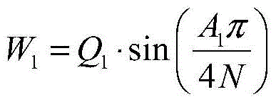
[0025] For the sinusoidal signal winding 4, the turns distribution is

[0026] W 1 = Q 1 · sin ( A 1 π 4 N )

[0027] For the cosine signal winding 5, the number of turns is distributed as

[0028] W 2 = Q 2 · sin ( A 1 π 4 N ...


PUM


Abstract

The invention discloses a harmonic-wave eliminating type radial magnetic circuit multipolar rotary transformer and a winding method of signal windings, belongs to the technical field of transformers and aims to solve the problem that a radial magneto-resistive type rotary transformer is low in precision, enlarged in size with increase of number of pole-pairs and limited in application field. Unequal air gaps are arranged between a stator and a rotor, 4NP stator grooves and 4NP stator teeth are processed on the inner surface of the stator axially, an excitation winding is disposed in the 4NP stator grooves, and sine and cosine signal windings are wound on the 4NP stator teeth. The method includes: optionally selecting a plane passing an axis of the stator and not intersecting with the stator teeth, uniformly dividing the 4NP stator teeth into 4P groups clockwise, from the plane, and winding the first group of N adjacent stator teeth anticlockwise, winding the N adjacent stator teeth clockwise, wherein winding modes of the sine and cosine signal windings are identical, and phase difference between the sine and cosine signal windings is a 90 electrical degrees. The rotary transformer and the winding method are applied to fields such as electric vehicles, aviation, aerospace and the like.

Description

technical field [0001] The invention relates to a harmonic elimination type radial magnetic circuit rotary transformer and a signal winding winding method, belonging to the technical field of transformers. Background technique [0002] Existing reluctance resolvers usually adopt a radial magnetic circuit structure, the excitation and signal windings are placed on the stator teeth, and the rotor adopts a salient pole structure. The excitation winding, sine signal winding and cosine signal winding adopt concentrated equal-turn winding, which simplifies the structure of the coil and facilitates mechanical winding. However, the resolver with this structure has defects such as low slot fill rate and large harmonic content, and its accuracy is lower than that of the wire-wound resolver. In addition, the precision of the resolver is significantly affected by the process such as the placement position of the coil. In addition, the existing radial reluctance rotary transformer not ...

Claims


Application Information

Patent Timeline
Patent Type & Authority Patents(China)
IPC IPC(8): H01F38/18H01F27/00H02K1/16H02K1/24H02K3/12
CPCY02T10/64
Inventor 尚静王昊丛宁刘承军赵猛邹继斌刘雪缘
Owner HARBIN INST OF TECH
Why Eureka
Try Eureka