
Locking ring type modular double excitation drive motor rotor production method

A technology for driving motors and production methods, which is applied in the manufacture of motor generators, stator/rotor bodies, electromechanical devices, etc., which can solve the problems of motor output torque, low efficiency, difficulty in winding coils, and high cost of motors, and achieve improved The effect of winding density, eliminating welding, and easy machine operation

Active Publication Date: 2022-06-21
SHANDONG UNIV OF TECH
View PDF14 Cites 0 Cited by
  • Summary
  • Abstract
  • Description
  • Claims
  • Application Information

AI Technical Summary

Problems solved by technology

[0002] At present, the production methods of the drive motor rotors used in electric vehicles mostly adopt the structure of rotor integration, such as the existing technology, patent name: a hybrid excitation synchronous motor with high power density, patent number: ZL201120422519.0, disclosed as follows The technical solution includes a rotor, a stator, an excitation winding and magnetic steel. The rotor core includes a first salient pole and a second salient pole. The poles include a first type permanent magnet and a second type permanent magnet. The first type permanent magnet and the second type permanent magnet are embedded in the first salient pole, and the field winding is wound around the second salient pole. The rotor adjacent to this structure If the interval between salient poles is too small, it is difficult to wind the coil, the cost of the motor is high, and the magnetic steel covers the entire salient pole. Under the action of the armature reaction of the impact current, irreversible demagnetization may occur, and the output torque and efficiency of the motor are low.

Method used


Image

  • Locking ring type modular double excitation drive motor rotor production method
  • Locking ring type modular double excitation drive motor rotor production method
  • Locking ring type modular double excitation drive motor rotor production method

Examples


Embodiment

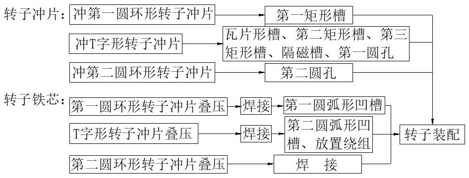
[0043] like Figure 1 to Figure 6 shown, including the following steps:

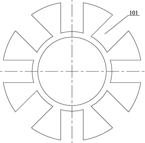
[0044] 1) Punching and cutting the first annular rotor punching piece 1, the first annular rotor punching piece 1 is evenly distributed with an even number of first rectangular grooves 101 penetrating through the axial thickness of the first annular rotor punching piece 1, the first The outer edge of a rectangular groove 101 is connected with the outer circle of the first annular rotor punch 1, the inner edge of the first rectangular groove 101 is not connected with the inner circle of the first annular rotor punch 1, and the inner edge of the first rectangular groove 101 is a concave surface Towards the arc shape of the center of the first annular rotor punch 1, a plurality of first annular rotor punches 1 are welded to form the first rotor core;

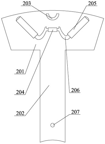
[0045] 2) Punching and shearing the T-shaped rotor punching sheet 2. The T-shaped rotor punching sheet 2 includes a transverse portion 201 and a longitudina...


PUM


Abstract

The invention provides a locking ring type modular double excitation drive motor rotor production method, which belongs to the technical field of automobile motors and electrical appliances. The locking ring-type modular double-excitation drive motor rotor core punching is easy to process, and the wire cutting path is less complicated; the off-line winding is easy to machine operation, convenient and fast, and the third rotor core is used as a locking ring, which can be used as A part of the magnetic circuit can realize the axial fixation of the modular rotor, and the effect of multi-winding and multi-permanent magnets can be achieved in the limited space inside the motor, thereby improving the power density of the motor; the magnet in the rotor structure adopts three layers The structure, the second permanent magnet steel and the third permanent magnet steel combined with the magnetic isolation groove can better play the role of magnetic circuit blocking, the first permanent magnet steel can play its magnetic attraction role, and weaken the high-order harmonic content of the back electromotive force of the drive motor , to improve the performance of the motor.

Description

technical field [0001] The invention provides a locking ring type modular double excitation drive motor rotor production method, which belongs to the technical field of automobile motors and electrical appliances. Background technique [0002] At present, the production methods of the drive motor rotors used in electric vehicles mostly adopt the structure of rotor integration, such as the existing technology, patent name: a hybrid excitation synchronous motor with high power density, patent number: ZL201120422519.0, disclosed as follows The technical solution includes a rotor, a stator, an excitation winding and magnetic steel. The rotor core includes a first salient pole and a second salient pole. The poles include a first type permanent magnet and a second type permanent magnet. The first type permanent magnet and the second type permanent magnet are embedded in the first salient pole, and the field winding is wound around the second salient pole. The rotor adjacent to thi...

Claims


Application Information

Patent Timeline
Patent Type & Authority Patents(China)
IPC IPC(8): H02K15/03
CPCH02K15/03
Inventor 胡文静张忠良张学义耿慧慧童拉念王爱传高艳红王善健高志东
Owner SHANDONG UNIV OF TECH
Learn More