Pot handle with view screen body

A video screen and ear technology is applied in the field of pot ears with video screen body to achieve the effect of simple structure

Inactive Publication Date: 2012-09-19
徐光启
View PDF5 Cites 1 Cited by
  • Summary
  • Abstract
  • Description
  • Claims
  • Application Information

AI Technical Summary

Problems solved by technology

[0002] The pot ears are a part of woks and soup pots. In the past, the pot ear

Method used


Image

  • Pot handle with view screen body
  • Pot handle with view screen body

Examples


Embodiment Construction

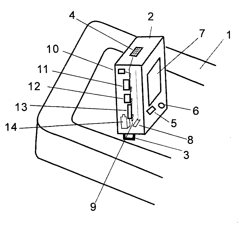
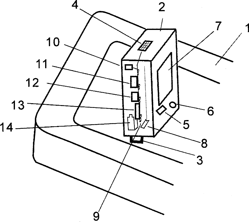
[0012] figure 1 Shown is the patent of the present invention, the specific embodiment of the pot ear with the screen body, which includes the pot ear 1, the screen body 2, and the buckle 3.

[0013] There is a video screen body 2 on the described pot ear 1, which includes a microphone 4, a timer 5, a switch 6, a liquid crystal screen 7, a copper-platinum shielding layer 8, a PCB board 9, a connection port 10, a decoding chip 11, and a firmware storage core Sheet 12, FLASH chip 13, screen body battery 14.

[0014] Timer 5, switch 6, liquid crystal screen 7 are on the surface of viewing screen body 4. Behind the liquid crystal screen 7, there is a copper-platinum shielding layer 8, and there is a PCB board 9 behind the copper-platinum shielding layer 8, which is connected to the PCB board 9, including a wiring port 10, a decoding chip 11, a firmware storage chip 12, and a FLASH chip 13 , video screen body battery 14, microphone 4.

[0015] The specific implementation process ...


PUM


Abstract

The invention discloses a pot handle with a view screen body. The pot handle comprises a pot handle (1), a view screen body (2) and a buckle (3). The view screen body (2) is arranged on the pot handle (1), and the pot handle (1) comprises a microphone (4), a timer (5), a switch (6), a liquid crystal screen (7), a copper-platinum shielding layer (8), a PCB (printed circuit board) (9), a wiring port (10), a decoding chip (11), a firmware memory chip (12), a FLASH chip (13) and a view screen body battery (14). The timer (5), the switch (6) and the liquid crystal screen (7) are arranged on the surface of the view screen body (2). The copper-platinum shielding layer (8) is arranged at the back of the liquid crystal screen (7), the PCB (9) is arranged behind the copper-platinum shielding layer (8), and the PCB (9) is connected with the wiring port (10), the decoding chip (11), the firmware memory chip (12), the FLASH chip (13), the view screen body battery (14) and the microphone (4). The buckle (3) is used for clamping the view screen body (2) on the pot handle (1). After the structure is adopted, a user can simultaneously appreciate various view screen programs, in particular to cooking programs during cooking, the timer on the screen can facilitate the calculation of the retention time of a dish in a hot pot or the soup stewing time. The pot handle disclosed by the invention has a simple structure, and can effectively enable people to effectively utilize time intervals during stewing and frying for studying and appreciating the various view screen programs, in particular to the cooking programs, study and grasp immediately and enable the dish frying to become simple and interesting.

Description

1. Technical field [0001] The patent of the present invention relates to a pot ear, in particular to a pot ear with a screen body. 2. Background technology [0002] The pot ear is an integral part of the wok and soup pot. In the past, the pot ear only had the heat insulation function for conveniently carrying the pot. 3. Contents of the invention [0003] The purpose of the patent of the present invention is to provide a pot ear with a video screen body, which not only has the heat insulation function of conveniently serving the pot, but also allows people to enjoy various video programs when cooking, especially some video programs that teach you how to cook. [0004] In order to achieve the above purpose, the patent of the present invention is realized through the following technical solutions: [0005] A pot ear with a screen body, which includes a pot ear, a buckle, and a screen body. [0006] There is a video screen body on the pot ear with a video screen body, which...

Claims


Application Information

Patent Timeline
IPC IPC(8): A47J36/00
Inventor 徐光启
Owner 徐光启
Why Eureka
Try Eureka