Stethoscope listening head
A technology of stethoscope and body, applied in the field of medical equipment accessories, can solve the problems of high cost, low work efficiency and high tool cost
- Summary
- Abstract
- Description
- Claims
- Application Information
AI Technical Summary
Problems solved by technology
Method used
Image
Examples
Embodiment 1
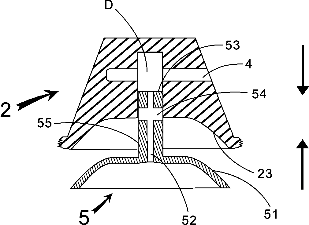
[0145] Embodiment 1: the following combination figure 1 The present invention is described further:
[0146] A stethoscope earpiece, comprising an earpiece body and a sound guide channel in the earpiece body. The sound guide channel includes a lower sound collecting surface 23 , a sound guide hole D and a side sound guide hole 4 . The lower sound collecting surface 23 , the sound guide hole D and the side sound guide hole 4 are arranged on the lower listening head body 2 .
[0147] The sound-guiding layer is closely fitted on the lower sound-collecting surface 23; the sound-guiding layer is the first special-shaped hollow rivet 5, and the end outer surface 51 of the first special-shaped hollow rivet 5 matches and closely fits with the lower sound-collecting surface 23. The first special-shaped hollow rivet The outer surface of the rod portion 55 of the rivet 5 closely fits with the sound guide hole D.
[0148] Wherein the rod cavity 52 of the first special-shaped hollow ri...
Embodiment 21
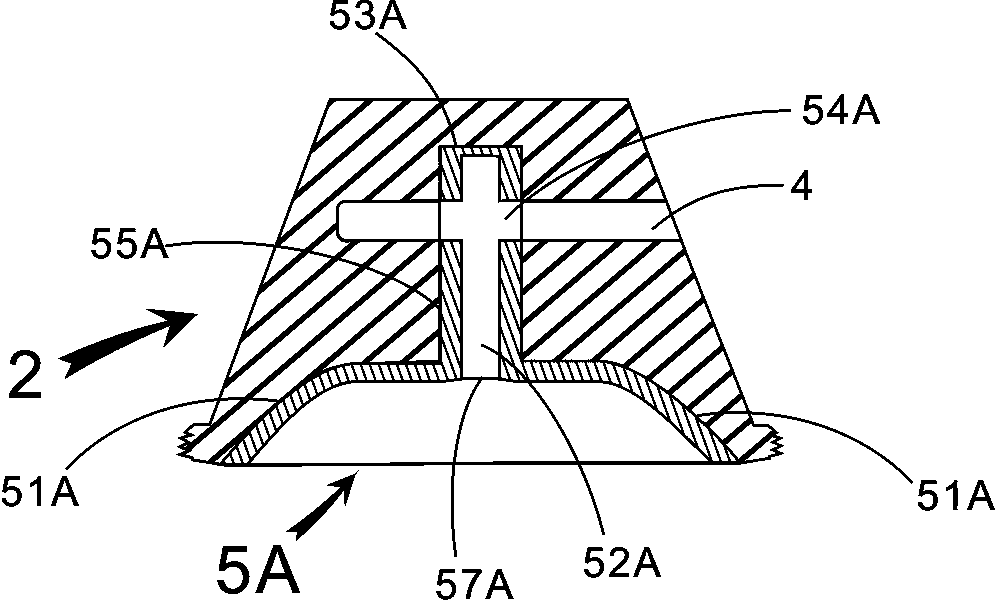
[0152] Example 2.1: the following combination figure 2 The present invention is described further;
[0153] A stethoscope earpiece, comprising an earpiece body and a sound guide channel in the earpiece body. The sound guide channel includes a lower sound collecting surface 23 , a sound guide hole D and a side sound guide hole 4 . The lower sound collecting surface 23 , the sound guide hole D and the side sound guide hole 4 are arranged on the lower listening head body 2 .
[0154] The sound-guiding layer is closely fitted on the lower sound-collecting surface 23; the sound-guiding layer is a special-shaped hollow rivet 5A, the outer surface 51A of the end of the special-shaped hollow rivet 5A coincides with the lower sound-collecting surface 23 and is closely matched, and the rod part 55A of the special-shaped hollow rivet 5A The outer surface is closely matched with the sound guide hole D. The rod cavity 52A of the special-shaped hollow rivet 5A runs through one end of th...
Embodiment 22
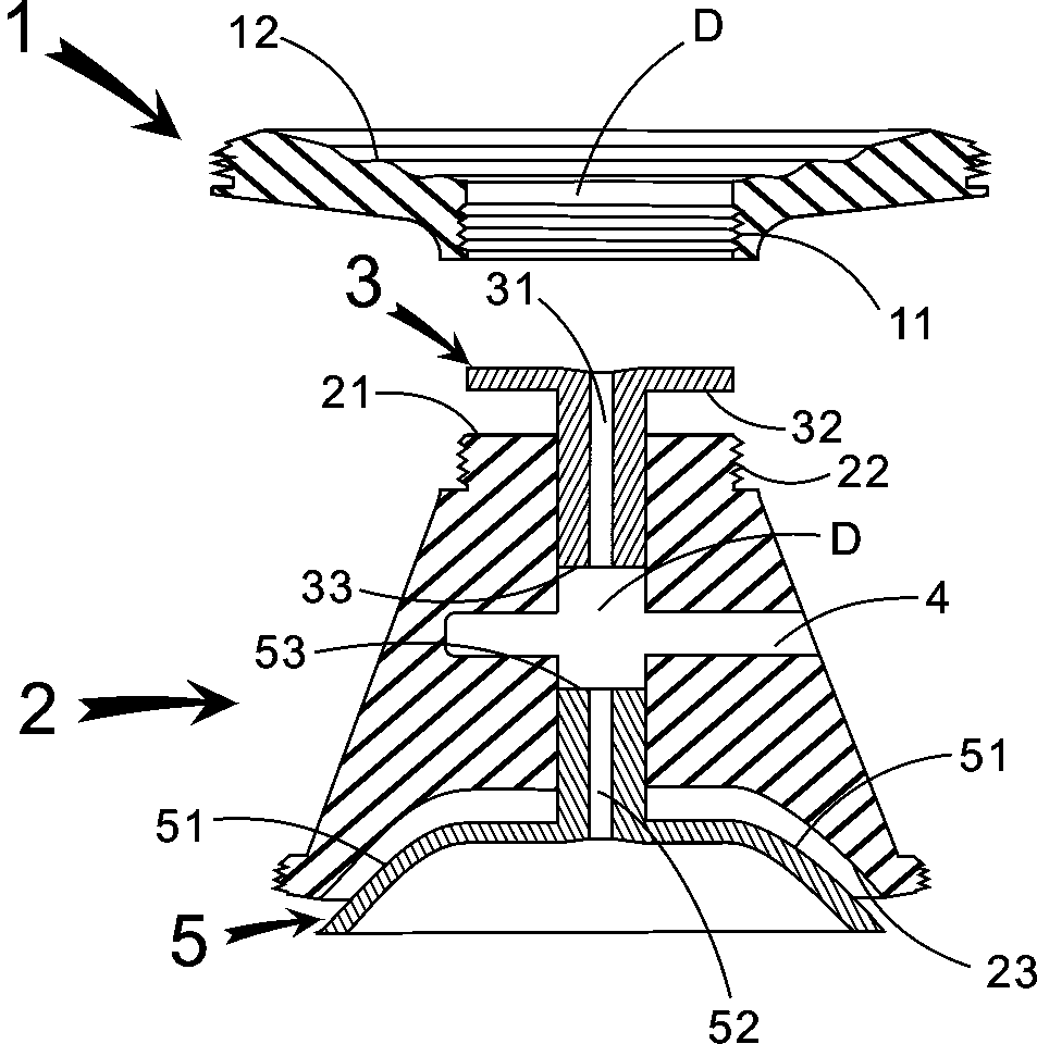
[0155] Example 2.2, combined below Figure 24 and Figure 31 The present invention is described further;
[0156] A stethoscope earpiece, comprising an earpiece body and a sound guide channel in the earpiece body. The sound guide channel includes a lower sound collecting surface 23 , a sound guide hole D and a side sound guide hole 4 . The lower sound collecting surface 23 , the sound guide hole D and the side sound guide hole 4 are arranged on the lower listening head body 2 .
[0157] The sound-guiding layer is closely fitted on the lower sound-collecting surface 23; the sound-guiding layer is the first special-shaped hollow rivet 5, and the end outer surface 51 of the first special-shaped hollow rivet 5 matches and closely fits with the lower sound-collecting surface 23. The first special-shaped hollow rivet The outer surface of the rod portion 55 of the rivet 5 closely fits with the sound guide hole D.
[0158] Wherein the rod cavity 52 of the first special-shaped holl...
PUM
 Abstract
Description
Claims
Application Information
 - R&D
- Intellectual Property
- Life Sciences
- Materials
- Tech Scout
- Unparalleled Data Quality
- Higher Quality Content
- 60% Fewer Hallucinations
Browse by: Latest US Patents, China's latest patents, Technical Efficacy Thesaurus, Application Domain, Technology Topic, Popular Technical Reports.
© 2025 PatSnap. All rights reserved.Legal|Privacy policy|Modern Slavery Act Transparency Statement|Sitemap|About US| Contact US: help@patsnap.com


