
Coating machine

A coating machine and coating technology, applied in the field of coating machines, can solve problems such as excessive energy consumption, uneven coating thickness, waste of energy, etc., and achieve the effects of maintaining stability, improving quality, and reducing wind energy.

Inactive Publication Date: 2012-09-19
ZHEJIANG KEXIANG WALLPAPER MFG
View PDF12 Cites 8 Cited by
  • Summary
  • Abstract
  • Description
  • Claims
  • Application Information

AI Technical Summary

Problems solved by technology

[0002] At present, the application of coating machine is more and more extensive. For example, the Chinese invention patent with publication number 102371229A discloses a new type of coating machine. Suspension tunnel structure, through the hot air blown by the upper and lower air knives, the substrate is suspended in the air in the oven without any contact with it. If this structure is applied to wallpaper, the energy is too large, and the coating thickness is likely to be uneven. The energy consumption is also too large. If the blast parallel to the horizontal plane is used, the heat transfer effect will become poor, and energy will also be wasted.

Method used


Image

  • Coating machine
  • Coating machine
  • Coating machine

Examples


Embodiment 1

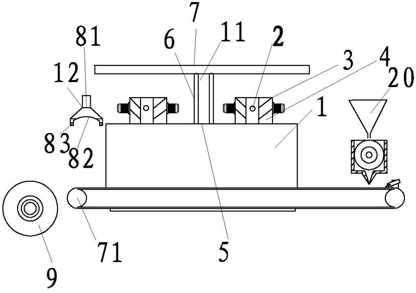
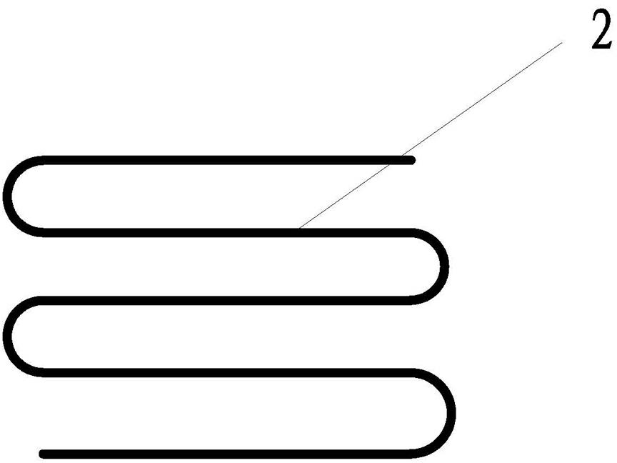
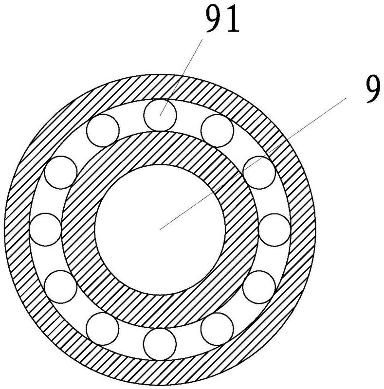
[0019] Example 1, such as figure 1 , 2 , shown in 3, a kind of coater, comprises feeding mechanism, material leading mechanism, coating mechanism, drying mechanism, exhaust mechanism, winding mechanism, and feeding mechanism is connected with coating mechanism by leading material mechanism, and coating structure and The winding mechanism is respectively arranged on the inlet side and the outlet side of the drying mechanism. The drying mechanism is provided with an exhaust mechanism. The drying mechanism is equipped with a transmission roller 71 for transmitting the carrier. Oven 1, a heating pipe 2 is arranged above the interior of the oven 1, and the heating pipe 2 is connected with the heating circulation system arranged outside the coating machine. The heating circulation system is an oil temperature system, and the heating pipe 2 is in the shape of a curve in the oven 1 Setting, two blowing devices 3 are arranged on both sides of the oven 1 close to the heating pipe 2...

Embodiment 2

[0022] Example 2, such as figure 1 , 2 , 3, the difference from Embodiment 1 is that the inclination angle formed between the guiding direction of the two wind direction guiding devices 4 and the horizontal plane is 0°-90°, which can be used in conjunction with the production process of other different products.


PUM


Abstract

The invention relates to the field of coating machines, in particular to a coating machine for producing wall paper. The coating machine comprises a feeding mechanism, a material guiding mechanism, a coating mechanism, a drying mechanism, an exhausting mechanism and a coiling mechanism, wherein the drying mechanism is also equipped with a transmission roller (71) for a transmission carrier; the drying mechanism also comprises a drying box (1) through which the transmission carrier passes; the heating tube (2) is arranged on the upper part of the inner part of the drying box (1); two blower device (3) are arranged on the drying box (1) and near the two sides of the heating tube (2) along the transmission direction; wind inlets of the blower devices (3) are oppositely formed; wind direction guiding devices (4) are arranged at the wind inlets; and the guiding directions of the two wind direction guiding devices (4) and the horizontal plane form 0-90-degree inclination angles with the same size and opposite directions. The coating machine is energy-saving and environment-friendly in structure and relatively high in coating precision.

Description

Technical field [0001] The invention involves the field of coating machines, which is specifically a coating machine for the production of wallpaper. Background technique [0002] At present, the application of the coating machine is becoming more and more widely used. For example, the Chinese invention patent with 102371229A has disclosed a new type of coating machine. The oven structure uses the air -floating tunnel structure.It will not have any contact with it in the air in the oven. If this structure is used in wallpaper, the energy is too large, which will easily make the coating unevenness and the energy consumption.The transmission effect of the thermal energy will become worse, and it will also waste energy. Invention content [0003] The purpose of the present invention is to provide a coating machine with energy saving and environmental protection and high coating accuracy. [0004] The above -mentioned technical purpose of the present invention is achieved through th...

Claims


Application Information

Patent Timeline
Patent Type & Authority Applications(China)
IPC IPC(8): B05C9/08B05C13/02B05D3/04
Inventor 金许翔
Owner ZHEJIANG KEXIANG WALLPAPER MFG
Learn More