
Steam-free passing water cooler

A water-penetrating cooler and steam condenser technology, applied in metal processing equipment, metal rolling, manufacturing tools, etc., can solve the problems of increasing air humidity, hidden dangers, waste of energy and water resources, etc., to ensure personal safety, The effect of improving working conditions and prolonging service life

Active Publication Date: 2012-09-19
湖南天益高技术材料制造有限公司
View PDF8 Cites 10 Cited by
  • Summary
  • Abstract
  • Description
  • Claims
  • Application Information

AI Technical Summary

Problems solved by technology

[0002] The controlled rolling process of rebar for construction is a well-known technology. Under the premise of not increasing the alloy content in the steel, the strength of rebar can be improved by using the water-through cooling controlled rolling technology; A large amount of steam will be generated on the surface of the high-temperature threaded steel bar, and the diffuse steam will cover the entire job site like superimposed white clouds, which greatly affects the sight of the workers on the job site and brings safety hazards
At the same time, because the steam floats in the air, the air humidity is increased, and the corrosion degree of the steel rolling equipment is aggravated. The floating of the steam also wastes energy and water resources.
People are aware of this problem, but there are no relevant reports on how to collect, condense and utilize this part of the steam

Method used


Image

  • Steam-free passing water cooler
  • Steam-free passing water cooler
  • Steam-free passing water cooler

Examples


Embodiment Construction

[0015] The specific implementation manners of the present invention will be further described in detail below in conjunction with the accompanying drawings.

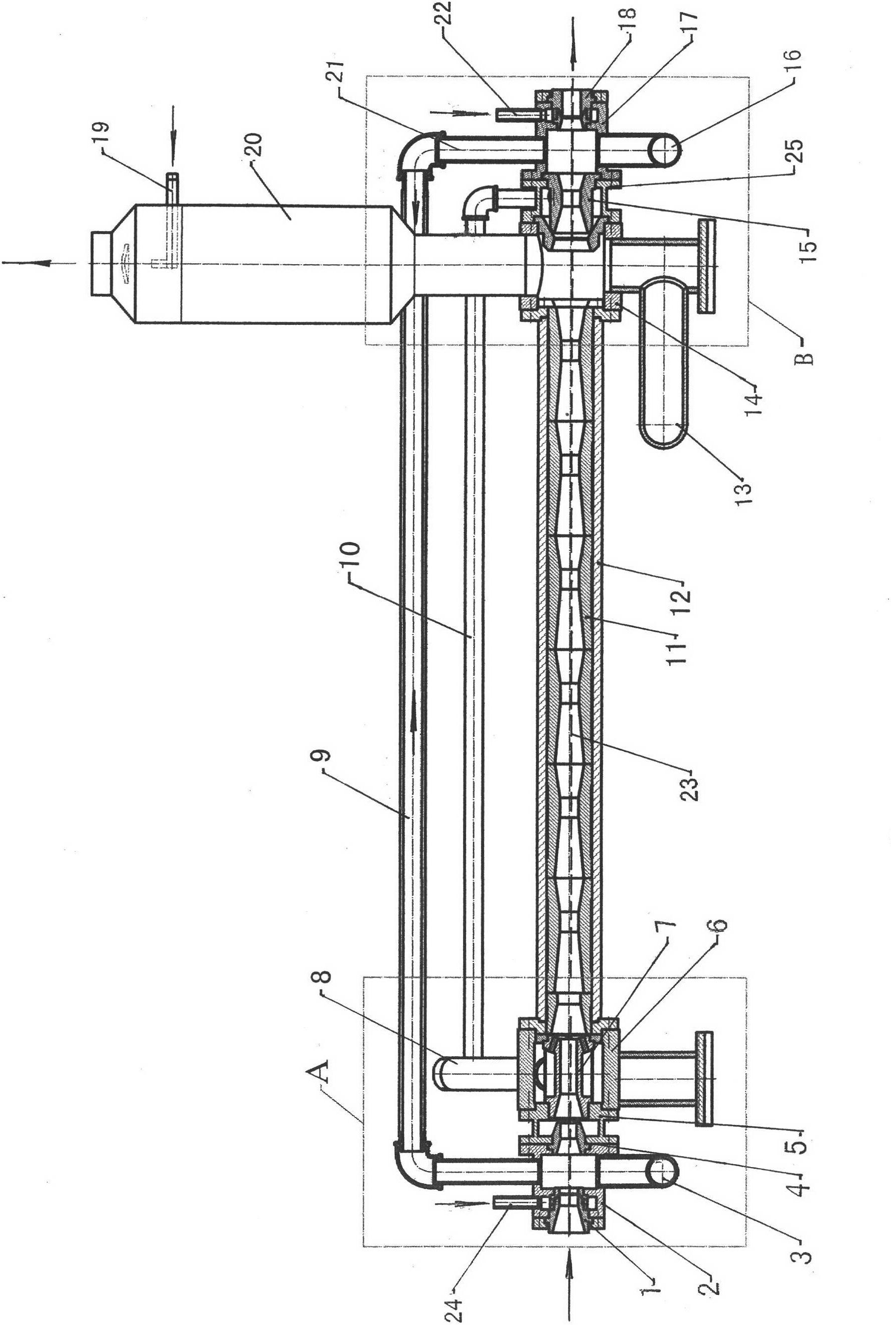
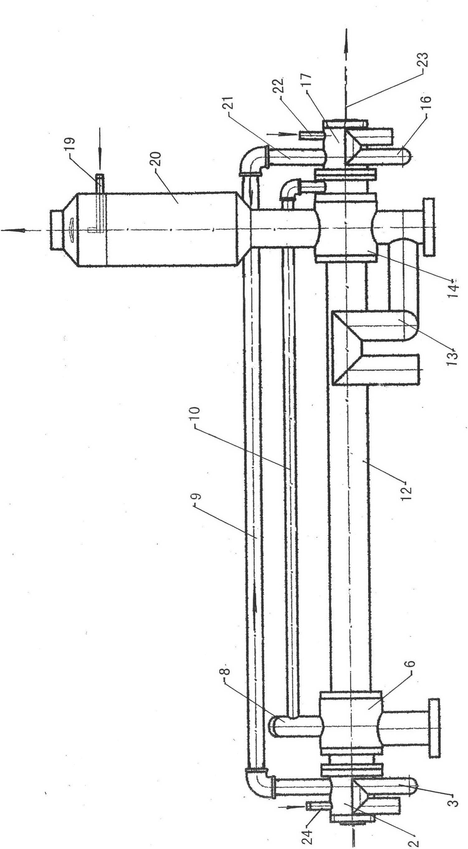
[0016] As shown in the accompanying drawings, the non-steam water-penetrating cooler includes a forward blowing air slit nozzle 1 and a reverse blowing air slit nozzle 18, a front steam / water separation box 2 and a rear steam / water separation box 17, an inlet End drain elbow 3 and outlet end drain elbow 16, transition conduit 4, return water balance box 5, nozzle box 6, left end cover plate 6a, cooling water nozzle 7, cooling water inlet pipe 8, front air / steam delivery pipe 9 And rear air / steam conveying pipe 21, counterattack water pipe 10, venturi tube 11, outer casing 12, main drainage pipe 13, main steam / water separation box 14, right end cover plate 14a, counterattack water annular seam nozzle 15, cooling water spray Pipe 19, steam condenser 20, front compressed air inlet pipe 24 and rear compressed air inlet pipe ...


PUM


Abstract

The invention discloses a steam-free passing water cooler. Two heads of a venture sleeved in an outer sleeve pipe are communicated with cooling water nozzles and the inner chamber of a main steam / water separation box, two ends of a center hole of a front steam / water separation box are respectively provided with a positive puffing split-jet injector and a transition catheter, two head of a front air / water delivery pipe are respectively communicated with the front steam / water separation box and the inner chamber of a steam condenser, a backwater balance box is sleeved with a nozzle box, and the plurality of cooling water nozzles are arranged on the nozzle box. The upper side wall of the main steam / water separation box is provided with the steam condenser, the cooling water nozzles are communicated with the inner chamber of the steam condenser, a main drainage pipeline is communicated with the lower side of the main steam / water separation box, a negative puffing water ring split-jet injector extends into the inner chamber of the main steam / water separation box, a negative puffing water pipe on a negative puffing water box is communicated with a cooling water inlet pipe, a back air / steam delivery pipe on a back steam / water separation box communicated with the negative puffing water box is communicated with the steam condenser, and a negative puffing split-jet injector is sleeved at the center of the back steam / water separation box. The condensed steam can be collected, and the service life of equipment can be prolonged.

Description

technical field [0001] The invention relates to a cooler, in particular to a non-steam through-water cooler which can be used in the pressure processing process of building threaded steel for controlling rolling to eliminate steam leakage. Background technique [0002] The controlled rolling process of rebar for construction is a well-known technology. Under the premise of not increasing the alloy content in the steel, the strength of rebar can be improved by using the water-through cooling controlled rolling technology; A large amount of steam will be generated on the surface of the high-temperature threaded steel bar, and the diffuse steam will cover the entire operation site like superimposed white clouds, which greatly affects the sight of the operators on the operation site and brings safety hazards. At the same time, because the steam floats in the air, the humidity of the air is increased, and the corrosion degree of the steel rolling equipment is aggravated. The floa...

Claims


Application Information

Patent Timeline
IPC IPC(8): B21B45/02
Inventor 赵勇张农钢
Owner 湖南天益高技术材料制造有限公司
Learn More