Pipe-cutting feeding device

A tube cutting and tube material technology, applied in the field of automatic feeding devices, can solve the problems of low degree of automation, low work efficiency, high labor intensity, etc.

Inactive Publication Date: 2012-09-19
SHENZHEN CEMCN
View PDF6 Cites 13 Cited by
  • Summary
  • Abstract
  • Description
  • Claims
  • Application Information

AI Technical Summary

Problems solved by technology

Its disadvantages are: it cannot be adjusted according to the diameter and length of the pipe material, and the pipe material with a short length can only be lifte

Method used


Image

  • Pipe-cutting feeding device
  • Pipe-cutting feeding device
  • Pipe-cutting feeding device

Examples


Example Embodiment

[0010] The automatic feeding device for cutting pipes of the present invention will be further described in detail below through specific embodiments.

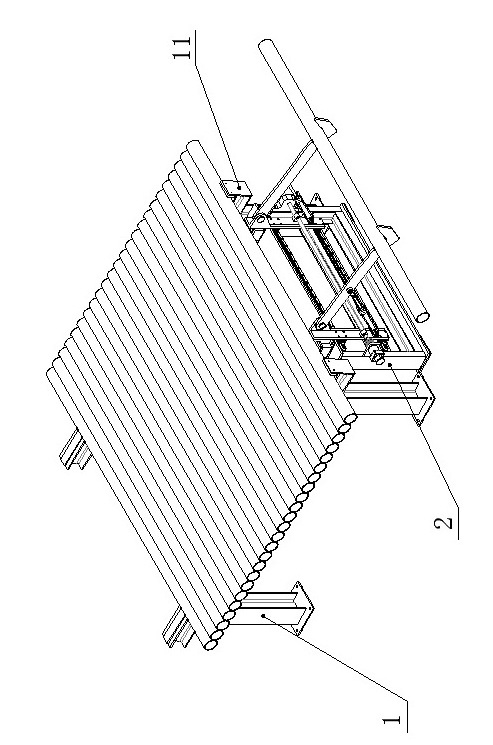
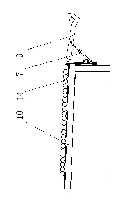
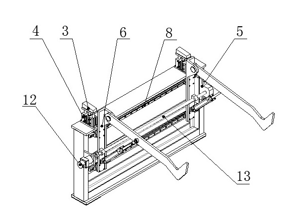
[0011] Such as Figure 1-Figure 2 As shown, the automatic pipe cutting and feeding device includes a tube storage rack 1 and a loading rack 2. The tube storage rack 1 is provided with a baffle 11 and an inclined raceway 10, and the loading rack 2 is provided with two sets of pallets 3. The pallet 3 is connected with the jacking cylinder 4, and the side of the loading rack 2 is also provided with two sets of lifting raceway devices 5, the lifting raceway device 5 is connected with the raceway support 6, the motor 12 and the screw 13, the raceway One end of the support 6 is connected with the lifting arm 9 and the other end is connected with the lifting cylinder 7. The middle part of the raceway support 6 is connected with the screw rod 13. The loading rack is also provided with two sets of guide rails 8, and the lifting arm 9 is p...


PUM


Abstract

The invention relates to a steel pipe-cutting feeding device. The steel pipe-cutting feeding device comprises a pipe storage rack and a feeding rack, wherein the feeding rack is provided with a pair of parallel supporting plates; the supporting plates is shaped like a rightward turned V; the bottoms of the supporting plates are connected with a cylinder; a lifting rollway is arranged on the side of the feeding rack and is connected with a guide rail; the guide rail is connected with a pair of parallel rollway supports; the rollway supports are connected with a screw rod; the feeding rack is connected with a motor; the motor drives the rollway supports to slide on the guide rail; the lifting rollway is provided with a lifting arm; a V-shaped bracket is arranged on the end part of the lifting arm; one end of the lifting arm is hinged with the rollway supports and the other end of the lifting arm is connected with a lifting cylinder; and the cylinder jacks one end of the lifting arm to rotate around the hinge end and realize lifting motion. The steel pipe-cutting feeding device can be applied to automatic feeding of a steel pipe cutter, has a compact structure, is simple to control, adapts to the pipes of different length and diameter, improves the production efficiency and reduces the labor intensity of workers.

Description

technical field [0001] The invention relates to an automatic feeding device for transporting pipe material or roller material to processing equipment, in particular to a pipe cutting and feeding device for mining "belt conveyor DTII roller" production. Background technique [0002] The existing pipe cutting and feeding device usually adopts a fixed turning transmission device to transport the steel pipe to the processing equipment. This structural device is two groups of parallel turning arms fixed on the rotating shaft. Its disadvantages are: it cannot be adjusted according to the diameter and length of the pipe material, and the pipe material with a shorter length can only be cut and loaded by workers or hoisted by a truck, which has low work efficiency, high labor intensity, and low degree of automation. Contents of the invention [0003] The technical problem to be solved by the present invention is to provide a steel pipe cutting and feeding device that can meet diffe...

Claims


Application Information

Patent Timeline
IPC IPC(8): B23Q7/00
Inventor 不公告发明人
Owner SHENZHEN CEMCN
Why Eureka
Try Eureka