Foam pump and liquid distributing ejector with same

A foam pump and liquid technology, applied in the field of foam pumps, can solve the problems of affecting the foaming performance and limited height, and achieve the effects of improving the utilization rate, low cost and fast processing speed.

Active Publication Date: 2014-08-06
DERJIN (JIANGSU) PLASTIC PACKAGING CO LTD
View PDF8 Cites 0 Cited by
  • Summary
  • Abstract
  • Description
  • Claims
  • Application Information

AI Technical Summary

Problems solved by technology

[0009] The first object of the present invention is to provide a foam pump to solve the problem in the prior art that the height of the gas-liquid mixing chamber is limited and the foaming performance is affected when the height of the entire foam pump is limited.

Method used


Image

  • Foam pump and liquid distributing ejector with same
  • Foam pump and liquid distributing ejector with same
  • Foam pump and liquid distributing ejector with same

Examples


example 1

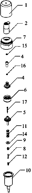
[0064] see figure 1 - Figure 4 , a kind of foam pump, in order to absorb the liquid in the container and make this liquid spray foam from the nozzle, the driving device is a pressure head, the foam former includes one or more screens and a gas-liquid mixing chamber arranged on the discharge channel , the liquid chamber pump unit includes a main column 5, a large piston 6, an upper pressing rod 17, a connecting rod 8, a small piston 9, and a cylinder 10. Including air valve 4, the following examples illustrate.

[0065] The shell is composed of outer cover 1, pressure head 2, screw cap 7 and cylinder 10, and the shell includes pressure head 2, screw cap 7, filter pipe 3, air valve 4, large piston 6, upper pressure rod 17, main column 5, retaining ring 14, small piston 9, connecting rod 8, cylinder 10, spring 11 and valve 12, filter screen pipe 3 is set between pressure head 2 and air valve 4, spring 11 is arranged outside main column 5, wherein:

[0066] A pressure head 2, ...

example 2

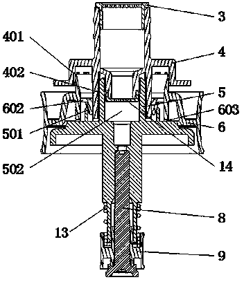
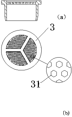
[0080] see again Figure 5 to Figure 8, a kind of foam pump, in order to absorb the liquid in the container and make this liquid eject foam from the nozzle, comprise pressure head, air valve and filter screen support, the nozzle hole is arranged in the pressure head, the air valve is arranged below the nozzle hole, A liquid spray channel is formed between the spray hole and the air valve, and the air valve can be provided with a filter screen support at the inlet and / or outlet of the liquid spray channel, and the filter screen holes on the filter screen support are in the shape of hexagonal holes.

[0081] The air valve is provided at the outlet of the spray channel. The filter screen bracket includes a support ring 32 arranged on the outer wall 41 of the air valve, an inner wall unit 34 and a filter screen unit 33 attached to the inner wall of the air valve, and the support ring 34 is connected to the inner wall unit 34 , the screen unit 33 is located above the inner wall uni...

example 3

[0087] The filter screen support can also be realized by adopting the following structure. see Figure 9A , Figure 9B , Figure 9C , the filter screen support includes an upper end portion 231, a middle block 233 and a lower end portion 232, wherein the upper end portion 231 and the lower end portion 232 are facing in the same direction, and are respectively located above and below the liquid spray channel, and a part of the liquid spray channel is occupied laterally to form a mixed cavity, the middle block 233 is located between the upper end portion 231 and the lower end portion 232, and its setting direction is opposite to that of the upper end portion and the lower end portion, and it is placed in the liquid spray channel laterally, and the part of the liquid spray channel left empty at the upper end is connected to the middle A first channel is formed between the blocks, and a second channel is formed between the part of the liquid spray channel left empty at the lower...


PUM


Abstract

The invention discloses a foam pump which comprises a liquid chamber pump unit, an air chamber pump unit, a foam forming device and a driving device, wherein the foam forming device comprises one or a plurality of screen nets arranged on a discharge channel and an air-liquid mixing chamber; the liquid chamber pump unit comprises a liquid chamber and a liquid chamber linking device; the liquid chamber linking device is used for conveying liquid from the liquid chamber to the air-liquid mixing chamber through a liquid conveying channel under the linkage of the driving device; the air chamber pump unit comprises an air chamber and an air chamber linking device; the air chamber linking device is used for conveying air from the air chamber to the air-liquid mixing device under the action of the driving device; the the air chamber pump unit comprises a resetting unit which is directly arranged in the air chamber; the liquid chamber linking device comprises a material discharge valve which is arranged at the interaction part of the liquid conveying channel and the air-liquid mixing chamber. Because the material discharge valve is arranged at the interaction part of the liquid conveying channel and the air-liquid mixing chamber, the liquid can directly enter the air-liquid mixing chamber through the liquid conveying channel, and can not be directly remained in a longer liquid conveying channel, and pollution is not caused.

Description

technical field [0001] The present invention relates to a foam pump and more particularly to a dispensing liquid sprayer comprising the foam pump. Background technique [0002] The existing foam pump is composed of a suction cylinder and a suction liquid cylinder whose outlets are connected. The suction cylinder is composed of a cylinder body and a piston. When in use, press the pressure head to make the piston of the suction cylinder and the piston of the suction liquid cylinder work synchronously. The suction liquid cylinder sucks the emulsion of the container, and the suction cylinder sucks the air, and then the emulsion and air are combined at the outlet. Mixing becomes foam spraying, but this structure is costly. [0003] In addition, Patent No. ZL2005200636954 discloses another type of foam pump, which includes a cylinder body, a press head, a plug tube and a spring. The center and the air cylinder are located on the periphery of the liquid cylinder, the air cylinder...

Claims


Application Information

Patent Timeline
Patent Type & Authority Patents(China)
IPC IPC(8): B65D83/76B65D47/34
Inventor 王雅灿
Owner DERJIN (JIANGSU) PLASTIC PACKAGING CO LTD
Why Eureka
Try Eureka