
Force-measuring device of hoisting tool of crane based on fiber grating sensor

A technology of optical fiber grating and force measuring device, which is applied in the field of port machinery, engineering machinery equipment, and hoisting machinery. It can solve problems such as the inability to judge whether the distribution of hoisting weight is uniform, the influence of the response speed of alarm sensors, and the sensitivity of wire rope winding methods. Compact, quick response, avoiding the effect of excessive measurement error

Inactive Publication Date: 2012-09-19
TONGJI UNIV
View PDF8 Cites 1 Cited by
  • Summary
  • Abstract
  • Description
  • Claims
  • Application Information

AI Technical Summary

Problems solved by technology

[0003] (1) The resultant force on the spreader is measured, and it is impossible to judge whether the lifting weight is evenly distributed on the four twistlocks. In other words, the balance of the spreader cannot be ensured, and it is sensitive to the winding method of the wire rope;
[0004] (2) Due to the elasticity of the wire rope, the detection speed is not fast, and the information cannot be monitored in real time, and the response speed of the alarm sensor has a certain influence;
[0005] (3) Only the tension of the wire rope is monitored, and it is impossible to judge the situation below the spreader, and it is impossible to confirm the working condition that the twistlock is not fully locked, and this situation may cause the container to fall off the hook during hoisting

Method used


Image

  • Force-measuring device of hoisting tool of crane based on fiber grating sensor
  • Force-measuring device of hoisting tool of crane based on fiber grating sensor
  • Force-measuring device of hoisting tool of crane based on fiber grating sensor

Examples


Embodiment 1

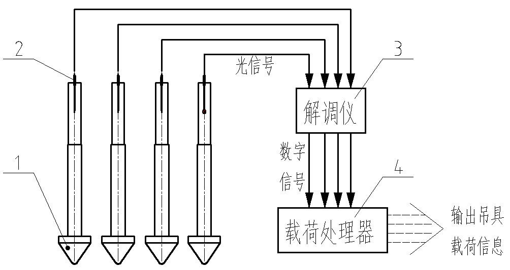
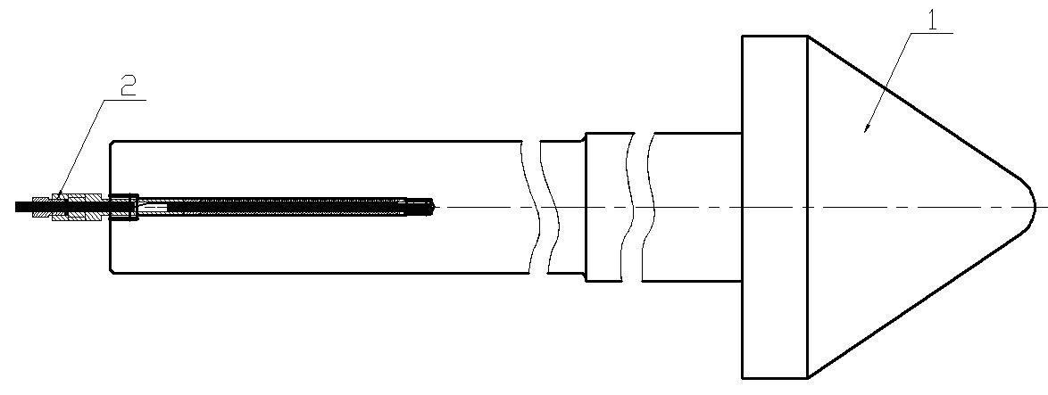
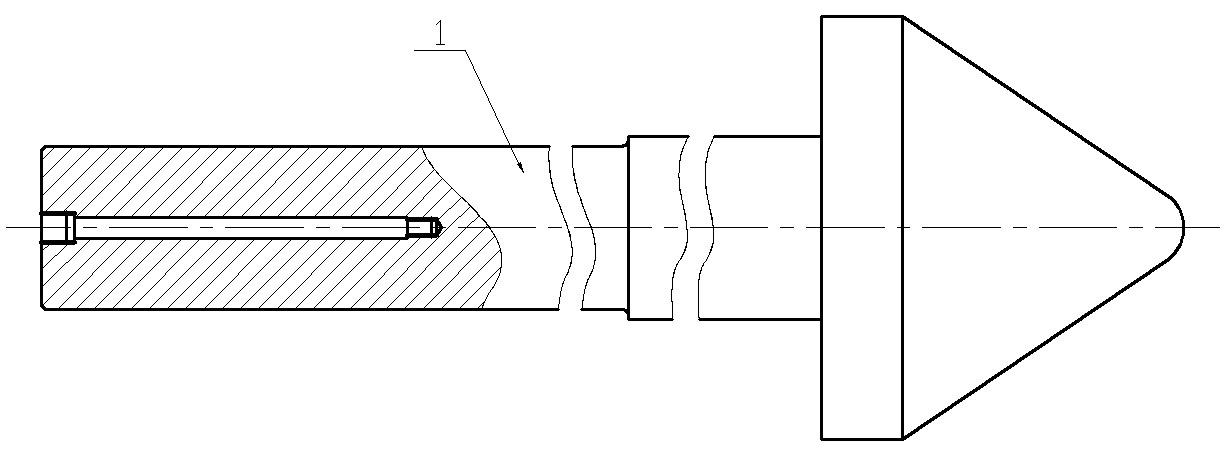
[0028] Embodiment 1: as Figure 1-Figure 4 As shown, it is composed of a modified twistlock 1, a fiber grating sensor 2, a demodulator 3, a load processor 4 and several wires 5, etc. The fiber grating sensor 2 is installed in the center of the axis of the modified twistlock 1 through threaded connection. The twistlock 1 needs to process an internal thread hole along the central axis at the top to connect with the external thread on the package shell of the fiber grating sensor. A fiber optic grating sensor 2 is installed on each of the four twistlocks of the container crane. Once the twistlock lifts the container, the fiber optic grating sensor 2 immediately detects the axial strain of the twistlock 1, and the wire of the sensor 1 is led out from the top of the twistlock 2. The detection signal is sent to the demodulator 3, and the demodulator 3 sends the digital signal to the load processor 4 to obtain the lifting load. The fiber grating sensor 2 is used to measure the hoist...


PUM


Abstract

The invention discloses a force-measuring device of a hoisting tool of a crane based on a fiber grating sensor, comprising a rotary lock, a fiber grating sensor, a demodulation instrument and a load processer, wherein one end of the fiber grating sensor is fixed on the axis of the end part of the rotary lock, the output end of the fiber grating sensor extends outside the upper end part of the rotary lock and is connected with the input end of the demodulation instrument through a conductor, the output end of the demodulation instrument is connected with the load processor and is used for transmitting signals after being demodulated to the load processor, and the load processor is used for processing digital singles of the demodulation instrument to be a load result of the rotary lock and outputting the result. The rotary lock is formed by rebuilding the conventional rotary lock. The upper end of the conventional rotary lock is provided with a fine long hole along the axis of the rotary lock, the bottom part and the end part of the hole are provided with internal threads, and the outer encapsulation of the fiber grating sensor is provided with external threads. The fiber grating sensor is screwed into the internal threads of the fine long hole arranged on the upper end of the rotary lock through the external threads on the fiber grating sensor. The force-measuring device of the hoisting tool of the crane has a compact structure, performances of fast response, high precision and good reliability, cannot be easily influenced by the external environment, and is extremely helpful for work safety and intelligence reconstruction of the cranes.

Description

technical field [0001] The invention belongs to the field of hoisting machinery, port machinery and engineering machinery equipment, and in particular relates to a force measuring device for a crane spreader based on an optical fiber grating sensor. Background technique [0002] When the container crane lifts the container, the four twist locks are respectively inserted into the four pin holes of the container, and then the twist locks are rotated, and the container is clamped by the lower end of the twist locks for lifting. At present, the main way to detect overload during the working process of the quay crane is to directly detect the force on the wire rope to judge whether it is overweight. However, this measurement method has the following main problems: [0003] (1) The resultant force on the spreader is measured, and it is impossible to judge whether the lifting weight is evenly distributed on the four twistlocks. In other words, the balance of the spreader cannot be...

Claims


Application Information

Patent Timeline
IPC IPC(8): B66C1/40
CPCB66C1/663B66C13/16
Inventor 张氢秦仙蓉胡建军张戬杰孙远韬廖鑫肖莹玥
Owner TONGJI UNIV
Learn More