Crane girder

A technology of cranes and main beams, which is applied in the field of cranes, can solve the problems of carts gnawing on rails, sliding carts, and trolleys climbing slopes, etc.

Inactive Publication Date: 2012-09-19
河南中州起重集团有限公司
View PDF5 Cites 6 Cited by
  • Summary
  • Abstract
  • Description
  • Claims
  • Application Information

AI Technical Summary

Problems solved by technology

[0002] Most of the main girders on the existing cranes still stay on the conventional combined welded box structure. The disadvantages are: many welds and heavy workload. , add welding ribs inside, and then weld the I-beam

Method used


Image

  • Crane girder
  • Crane girder

Examples


Embodiment Construction

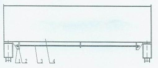
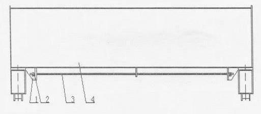
[0005] The embodiment is described in detail in conjunction with the above drawings. The two ends of the lower part of the main girder 4 are fixed with supporting supports 1 , and the tie rods 3 penetrate the middle of the supporting supports at both ends of the main girder and are fixed with tension nuts 2 . The best implementation is: the main girder is made of rectangular tubes, the rectangular tubes are cut into required lengths according to the span length of the main girders, the rectangular tubes pass through the arching machine once into a parabolic shape, and the upper camber is in the range of (0.9-1.4 ) between S / 1000, the supporting base welded at both ends of the main beam is connected with high-strength hinged bolts, the tie rod penetrates into the middle of the supporting base, and the torque is gradually increased in sequence with a special torque wrench, and the tie rod can also be replaced by a cable , adjust the initial stress of each prestressed tie rod to m...


PUM


Abstract

The invention discloses a crane girder. The crane girder comprises a girder, wherein supporting pedestals are fixed at two ends of the lower part of the girder made of a rectangular pipe; a pull rod passes through the middle part of the supporting pedestals at the two ends of the girder and is fixed by a tensioning nut; the rectangular pipe is subjected to one-step parabolic formation by an arch raising machine; the supporting pedestals fixed at the two ends of the girder made of the rectangular pipe are connected through a high-strength hinged bolt; the pull rod can also adopt a guy cable; and a thin steel plate cover with the same width as that of the girder is arranged at the lower part of the girder. The crane girder has the following effects that: welding deformation is reduced; almost no welding stress exists; the problem that the camber of the conventional girder is gradually reduced because the welding stress releases is solved; the self weight of the crane is 15 to 20 percent lighter than that of the conventional crane, so the problem about the initial investment of users is solved; and the wheel pressure is low, so the service life of a workshop is prolonged, the building cost of the workshop is reduced, welding materials such as welding rod flux and the like are greatly saved, industrial pollution is reduced and the manual manufacturing cost is reduced.

Description

Technical field: [0001] The invention relates to a main girder, which is especially suitable for use on a crane. Background technique: [0002] Most of the main girders on the existing cranes still stay on the conventional combined welded box structure. The disadvantages are: many welds and heavy workload. , add welding ribs inside, and then weld the I-beam rolling track used for hoist operation. Another example is that the main girder of the known double-girder crane adopts the upper and lower cover plates and two webs to splice. "Etc., prone to accidents and endangering safety. Invention content: [0003] The task of the present invention is to propose a crane girder with simple process, reduced welding deformation and reduced labor cost. The task of the present invention is accomplished like this, it comprises main girder, it is characterized in that: the main girder bottom two ends of rectangular pipe are fixed with supporting base, pull bar penetrates the middle of...

Claims


Application Information

Patent Timeline
IPC IPC(8): B66C6/00
Inventor 王西彦徐秉民王伟宾王伟义
Owner 河南中州起重集团有限公司
Why Eureka
Try Eureka