Quick-release positioning pin structure

A technology of positioning pins and cotter pins, applied to quick-action fasteners, bolts, etc., which can solve the problems of large force, heavy weight, and large aircraft parts required for pulling out positioning pins, and achieves convenient manual operation and reduced The effect of pulling out strength and convenient quick release and positioning

Inactive Publication Date: 2012-09-19
XIAN AIRCRAFT IND GROUP
View PDF5 Cites 13 Cited by
  • Summary
  • Abstract
  • Description
  • Claims
  • Application Information

AI Technical Summary

Problems solved by technology

[0003] Due to the large size and heavy weight of large aircraft components, during the docking process, the force required to pull out the positioning pins with large apertures is very large, and it is difficult to pull out manually, and it is difficult to use machinery at these assembly docking positions. Due to the current situation, it is urgent to find a new type of quick-release positioning pin to meet the needs of the aircraft process equipment assembly process.

Method used


Image

  • Quick-release positioning pin structure
  • Quick-release positioning pin structure
  • Quick-release positioning pin structure

Examples


Embodiment Construction

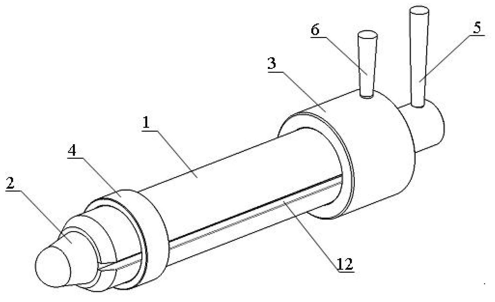
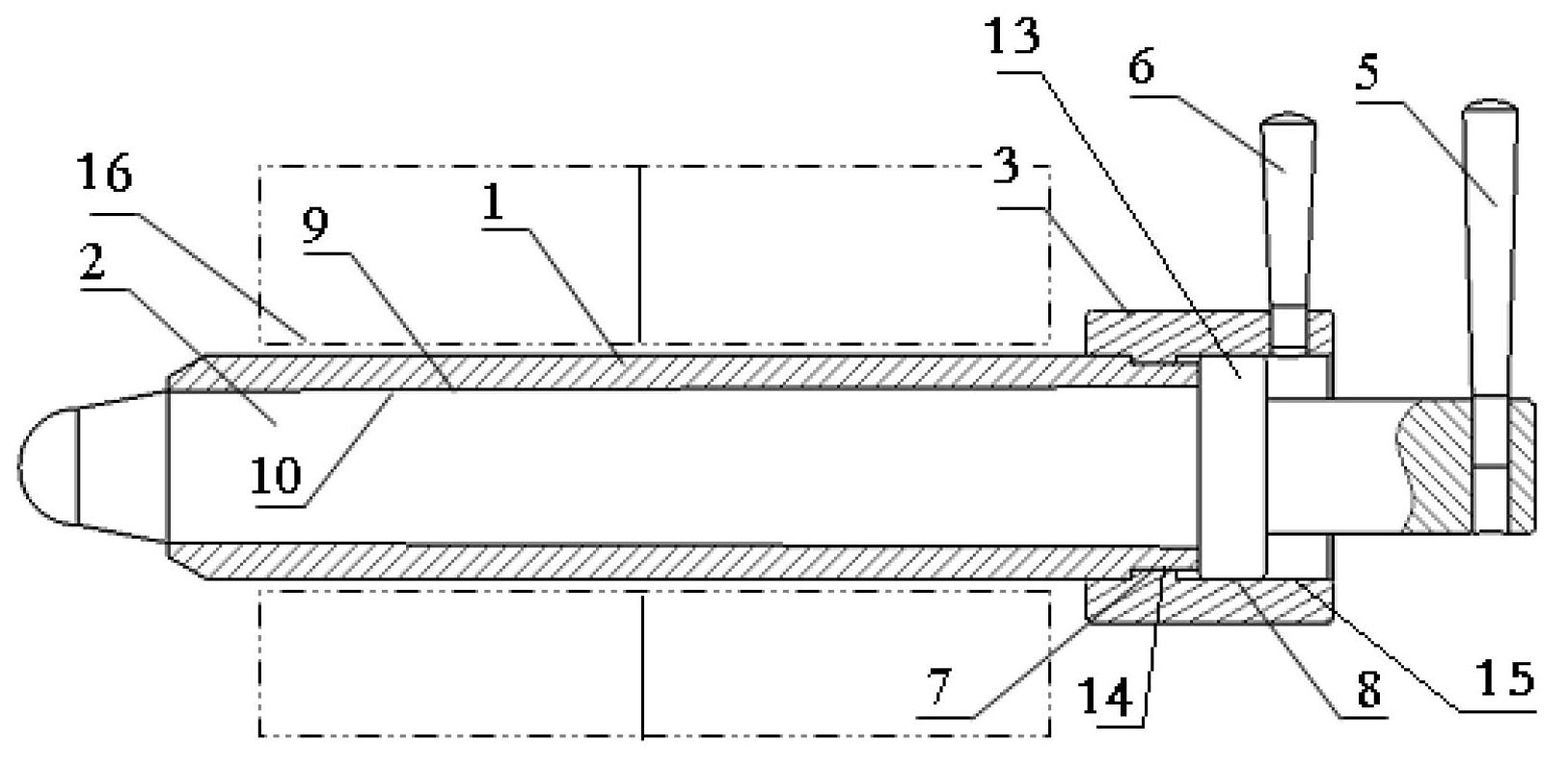
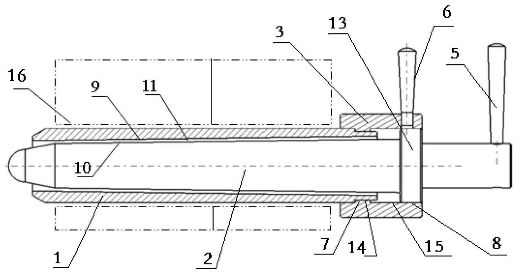
[0015] Referring to the accompanying drawings, the quick-release positioning pin of the present application is mainly composed of a positioning pin sleeve 1, a quick-release pin 2 and a quick-release screw sleeve 3. The positioning pin sleeve 1 is a cotter pin with a C-shaped opening 12, and the positioning pin sleeve 1 has a taper Inner cavity 9, one side opening end of positioning pin sleeve 1 is a tapered closing structure, to facilitate insertion in the positioning hole 16, the outside of the other side opening end of positioning pin sleeve 1 is provided with first external thread 7; The pin 2 is a solid structure with a tapered surface 10 matched with the tapered inner cavity 9 of the positioning pin sleeve 1. The front end of the quick release pin 2 is a spherical in-position structure, and the other end of the quick release pin 2 is provided with a protrusion near the end. The stepped shaft 13 has a second external thread 8 on the outer surface of the stepped shaft. It i...


PUM


Abstract

The invention discloses a quick-release positioning pin structure which is composed of a positioning pin sleeve, a quick-release pin and a quick-release screw sleeve. The positioning pin sleeve is in taper fitting with the quick-release pin, the quick-release screw sleeve is matched with external threads of the positioning pin sleeve and the quick-release pin respectively through internal threads, and force application handles are respectively arranged on the quick-release screw sleeve and the quick-release pin. Mechanical radial force of a butting hole site is transformed to axial force by utilizing taper, the condition that traditional cylindrical latch pin only has shearing force and friction force, the extraction strength of the cylinder pin is greatly reduced, manual operation is convenient, and a quick-release positioning function is realized.

Description

technical field [0001] The invention relates to the technical field of aircraft assembly, in particular to a quick-release positioning pin structure used for component docking. Background technique [0002] During the docking process of aircraft assembly sections or components, there are many docking holes, and the diameter of these holes is large, most of which are above 50mm. These butt holes are generally initial holes, and a certain amount of processing is reserved. In these connection holes, two or more positioning holes need to be selected, and these positioning holes are used to fix the position of the aircraft components. The positioning pins of these positioning holes are generally inserted with small diameter positioning pins (such as: less than the theoretical diameter of 0.2mm). After the pins have positioned the aircraft components, use the two holes as a reference to ream the rest of the holes with the drilling mold. The other refined holes are the reference ...

Claims


Application Information

Patent Timeline
Patent Type & Authority Applications(China)
IPC IPC(8): F16B19/02F16B21/06
Inventor 王守川李王豪周养萍
Owner XIAN AIRCRAFT IND GROUP
Why Eureka
Try Eureka