Damper pulley

A technology of pulleys and rims, applied in the direction of belts/chains/gears, springs/shock absorbers, components with teeth, etc., can solve problems such as heavy weight, restrictions, and complex structures, and achieve good friction resistance and impact resistance Effects of performance, adequate strength and durability

Inactive Publication Date: 2012-09-19
FUKOKU KOREA
View PDF6 Cites 3 Cited by
  • Summary
  • Abstract
  • Description
  • Claims
  • Application Information

AI Technical Summary

Problems solved by technology

However, although the damping pulley made of cast iron in the prior art has sufficient strength and durability, it has the disadvantage of being too heavy.
In particular, if the thickness of the spoke 6 is reduced in order to reduce the weight of the spoke 6 formed of cast iron of the damper pulley, the effective cross-sectional area is reduced due to air bubbles generated on the surface of the casting, so that the spoke 6 cannot secure sufficient strength. So reducing the thickness of the spoke 6 is also limited
[0005] In addition, in order to reduce the weight of the damper pulley, there have also been hubs made of plastic or steel plate, but such damper pulleys do not have the strength or durability to withstand the strong vibration or torque transmitted from the crankshaft. To remedy such fragility strength or durability, it is necessary to add a complex reinforcement structure, so the structure is complicated or the manufacturing is complicated, which has the disadvantage of increasing the manufacturing cost

Method used


Image

  • Damper pulley
  • Damper pulley
  • Damper pulley

Examples


Embodiment Construction

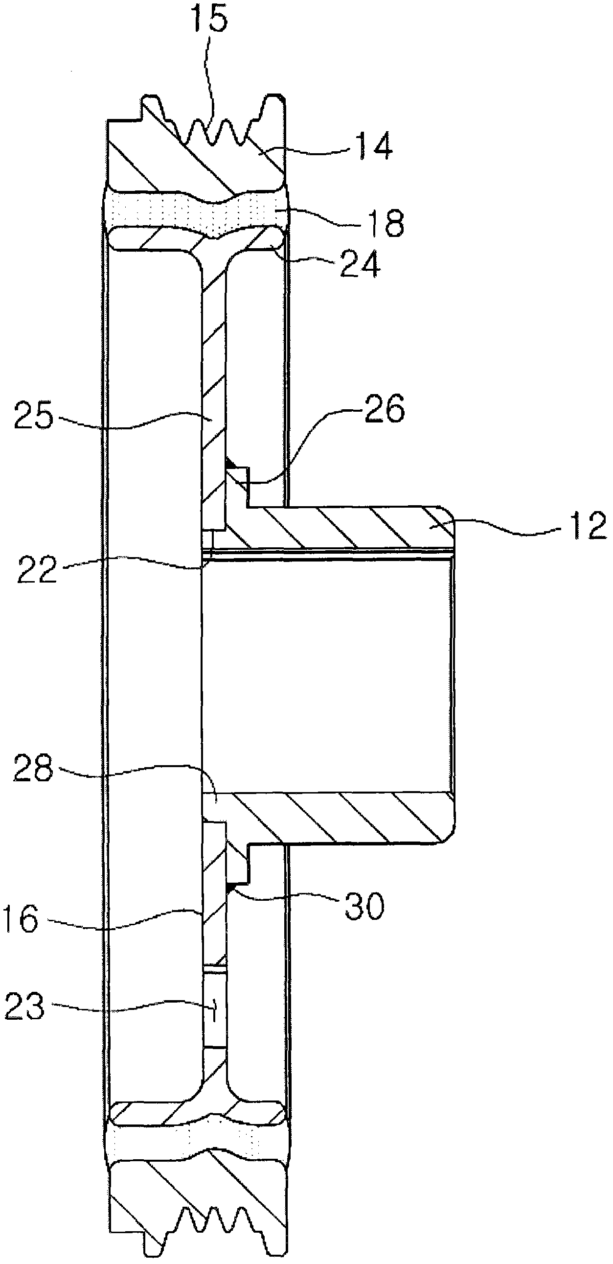
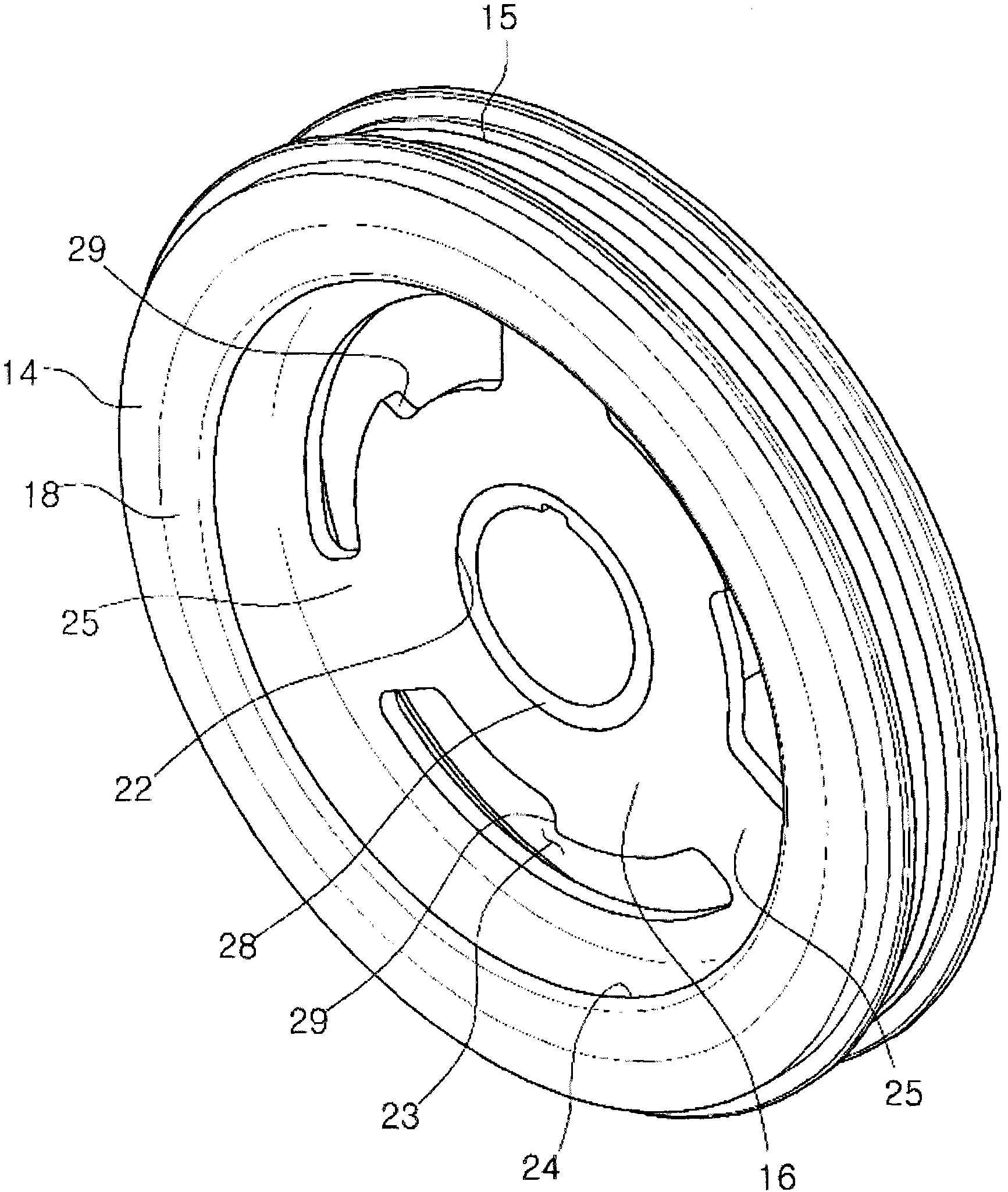
[0015] Hereinafter, the present invention will be described in detail with reference to the accompanying drawings. figure 2 is a cross-sectional view according to an embodiment of the present invention, image 3 and Figure 4 Schematic representations of one side and the other, respectively, of the described embodiment. As shown in the figure, the damping pulley according to the present invention includes: a hub 12, which is cylindrical and combined with a crankshaft; a hub spacer 16, which is combined with a peripheral portion of the hub 12, a central portion of the liner 16 is formed with a through hole 22, and a peripheral portion of the hub liner 16 is formed with a rim 24; a rubber layer 18 attached to the outer peripheral surface of the rim 24 of the hub liner 16; and The pulley 14 is attached to the outer surface of the rubber layer 18 .

[0016] The hub 12 according to the present invention is cylindrical and made of cast iron material, preferably, ductile iron wit...


PUM


Abstract

The invention relates to a damper pulley which comprises of a cylindrical hub (12) being made of cast iron and coupled to the crankshaft of the engine, a hub plate (16) being made of steel plate and having a central hole (22) on which the hub (12) is attached and a rim (24) at the periphery of it, a rubber layer (18) of a ring shape being attached on the rim (24) of the hub plate (16), and a pulley (14) attached on the outer surface of the rubber layer (18). The damper pulley is lightweight, and is manufactured easily with sufficient strength and durability.

Description

technical field [0001] The invention relates to a shock-absorbing pulley In more detail, it relates to a lightweight damping pulley mounted on a crankshaft of a vehicle engine, which is lightweight and easy to manufacture, and has required rigidity and durability. Background technique [0002] Generally, torque periodically acts on the crankshaft of the vehicle engine, so torsional vibration occurs. This torsional vibration increases as the rotational force of the crankshaft per cylinder increases, and increases as the length or stiffness of the crankshaft increases. When the crankshaft rotates at a certain number of revolutions, this torsional vibration resonates with the natural vibration of the crankshaft itself to form a strong vibration, which makes the ride uncomfortable and causes damage to the timing gear or the crankshaft. [0003] In order to reduce this torsional vibration, a torsional vibration reduction device integrally formed with the crankshaft pulley is p...

Claims


Application Information

Patent Timeline
Patent Type & Authority Applications(China)
IPC IPC(8): F16H55/36F16F15/124
CPCF16F15/126F16F15/12F16H55/36
Inventor 申承雨
Owner FUKOKU KOREA
Why Eureka
Try Eureka