Check patentability & draft patents in minutes with Patsnap Eureka AI!

Method for measuring positioning error of robot

A positioning error and robot technology, applied in the field of robot positioning error measurement, can solve the problem that the data acquisition process cannot be realized

Active Publication Date: 2012-09-19
SHANGHAI AIRCRAFT MFG
View PDF3 Cites 41 Cited by
  • Summary
  • Abstract
  • Description
  • Claims
  • Application Information

AI Technical Summary

Problems solved by technology

The accuracy of the "measurement tool" determines the measurement accuracy of the positioning error; the "coordinate unification of the measurement data" is based on the position of the center of the measurement target at the end of the robot (tool coordinate system) and the relationship between the robot base coordinate system and the coordinate system of the measuring equipment The transformation matrix (base coordinate system) is calibrated, and the measurement data of the end flange center directly obtained from the robot and the data of the target center measured by the measuring equipment are unified into one coordinate system, so as to obtain the positioning error of the sampling point; " The effectiveness of the selection of "measurement data samples" largely determines the efficiency and accuracy of robot structural parameter calibration. The more sufficient data collected according to the needs, the more conducive to the calibration process. However, assuming that each of the robot's 6 joints takes 5 joints Angle combination measurement requires 15625 measurements, which is impossible in the actual data collection process

Method used


Image

  • Method for measuring positioning error of robot
  • Method for measuring positioning error of robot
  • Method for measuring positioning error of robot

Examples


Embodiment Construction

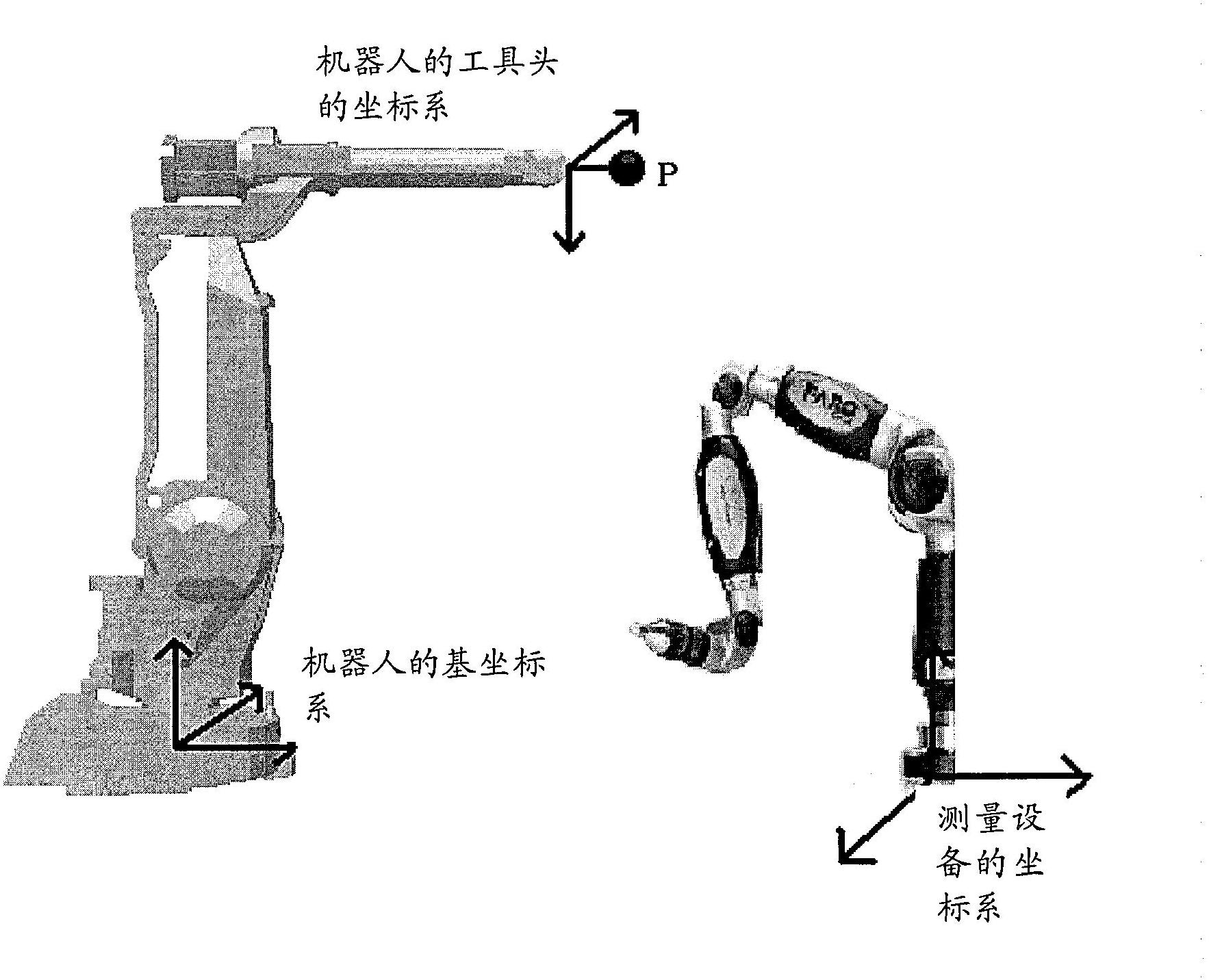
[0016] Positioning error measurement system of industrial robot based on FARO ARM

[0017] Such as figure 1 As shown, the industrial robot positioning error measurement system is composed of FARO ARM, measurement target and industrial robot. In the figure, P represents the target center to be measured, Base is the robot base coordinate system, Tool0 is the robot flange coordinate system, and Measure is the FARO ARM coordinate system.

[0018] In this industrial robot positioning error measurement system, FARO ARM can directly measure the coordinates of the target center P in the Measure coordinate system, and the robot itself can also be used as a measuring device to obtain the target center P grasped by the robot in the robot Base coordinate system The coordinates of the two can be unified into the same coordinate system through coordinate transformation, and then compared to obtain the position error of each measurement point of the industrial robot in its workspace. The...


PUM


Abstract

The invention discloses a method for measuring the positioning error of a robot. The method comprises the following steps of: providing measurement equipment and setting a measured reference point P; measuring the actual position of the measured reference point P in the coordinate system of the measurement equipment; converting the position of the measured reference point P in the flange coordinate system of the robot into a calculated position in the coordinate system of the measurement equipment by means of coordinate conversion, and calculating the difference between the actual position and the calculated position to obtain the positioning error.

Description

technical field [0001] The invention relates to a method for measuring robot positioning errors. Background technique [0002] The repetitive positioning accuracy of industrial robots is very high, but the absolute positioning accuracy is very poor. In order to improve the performance of the robot and expand the application range of industrial robots, it is necessary to calibrate the parameters of the robot kinematics model to reduce its absolute positioning error. Robot calibration is generally carried out in four steps: modeling, measurement, identification and compensation. The measurement of the absolute positioning error corresponding to the sampling point in the robot workspace is the premise of the calibration of the robot's structural parameters, and the validity of the measurement data determines whether the calibration of the robot parameters can be correctly realized. The process of robot absolute positioning error measurement generally includes the design and s...

Claims


Application Information

Patent Timeline
IPC IPC(8): G01B21/00
Inventor 方伟余蕾斌薛雷沈立恒
Owner SHANGHAI AIRCRAFT MFG
Features
  • R&D
  • Intellectual Property
  • Life Sciences
  • Materials
  • Tech Scout
  • Unparalleled Data Quality
  • Higher Quality Content
  • 60% Fewer Hallucinations
Learn More