Compound type zone plate photon sieve

A zone plate and photon sieve technology, applied in the field of diffractive optical elements, can solve the problems of poor imaging contrast and low diffraction efficiency, and achieve the effects of improving imaging contrast, improving diffraction efficiency, suppressing side lobe effects and advanced diffraction.

Inactive Publication Date: 2012-09-19
INST OF MICROELECTRONICS CHINESE ACAD OF SCI
View PDF5 Cites 6 Cited by
  • Summary
  • Abstract
  • Description
  • Claims
  • Application Information

AI Technical Summary

Problems solved by technology

[0005] Although large-aperture photon sieves have broad application prospects in the field of ultraviole...

Method used


Image

  • Compound type zone plate photon sieve
  • Compound type zone plate photon sieve
  • Compound type zone plate photon sieve

Examples


Embodiment Construction

[0023] In order to make the object, technical solution and advantages of the present invention clearer, the present invention will be described in further detail below in conjunction with specific embodiments and with reference to the accompanying drawings.

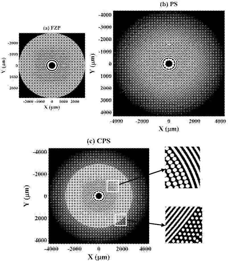
[0024] The composite zone plate photon sieve provided by the present invention includes a light-transmitting substrate and an opaque metal film plated thereon, and a series of light-transmitting annular zones and several Light-transmitting holes. By embedding a zone ring in the middle 2 / 3 of the traditional photonic sieve, the composite zone plate photonic sieve designed in this way increases the diffraction efficiency by 70% while maintaining the good focusing characteristics of the traditional photonic sieve, and improves the imaging contrast.

[0025] In the composite zone plate photonic sieve, the material of the light-transmitting substrate can also be light-transmitting materials such as ordinary glass or plexiglas...


PUM

PropertyMeasurementUnit
Thicknessaaaaaaaaaa

Abstract

The invention discloses a compound type zone plate photon sieve which comprises a light-transmitting substrate and a lighttight metal film coated on the light-transmitting substrate. A series of light-transmitting ring strips and a plurality of light-transmitting small holes are distributed on the lighttight metal film. The diameter of each light-transmitting small hole is 1.5 times the width of the corresponding zone plate ring strip. Relative to zone plates, the light-transmitting small holes which are distributed randomly enable diffraction light to mutually interfere so that the side lobe effect and high-order diffraction can be effectively inhibited, the resolution is improved, and a sharp focal spot is obtained. The zone plates are embedded on 2/3 of middle portion of the compound type zone plate photon sieve on the basis of an ordinary photon sieve so that the transmittance is improved, the diffraction efficiency is improved, and the imaging contrast is improved.

Description

technical field [0001] The invention relates to the technical field of diffractive optical elements, in particular to a composite zone plate photon sieve. Background technique [0002] The photon sieve is a new type of diffractive optical element based on the Fresnel zone plate. It replaces the area corresponding to the bright ring on the Fresnel zone plate with a large number of randomly distributed light-transmitting small holes, and the diameter of the small holes is the corresponding 1.5 times the width of the zone plate ring. These light-transmitting small holes randomly distributed in the position make the diffracted light interfere with each other, which can effectively suppress the side lobe effect and advanced diffraction, improve the resolution, and obtain a sharper focal spot. [0003] The resolution of the traditional zone plate in the imaging field depends on the width of its outermost ring, which is limited by the processing technology, so it is difficult to f...

Claims


Application Information

Patent Timeline
IPC IPC(8): G02B5/18G02B1/10
Inventor 谢常青辛将朱效立刘明
Owner INST OF MICROELECTRONICS CHINESE ACAD OF SCI
Why Eureka
Try Eureka