Integrated control device and control method for hydraulic system

A hydraulic system, integrated control technology, applied in liquid level control, non-electric variable control, control/regulation system, etc., can solve the problem of inability to meet the requirements of industrial hydraulic systems, limited input and output channels, and difficulty in system-level expansion, etc. problems, to achieve the effect of simple function expansion and deformation design, simplifying design and improving development efficiency

Inactive Publication Date: 2012-09-19
ZHEJIANG UNIV
View PDF5 Cites 5 Cited by
  • Summary
  • Abstract
  • Description
  • Claims
  • Application Information

AI Technical Summary

Problems solved by technology

[0002] The current hydraulic system control in industrial applications is mainly controlled by the combination of PLC, relay and proportional amplifier board. The PLC output signal controls the relay output switch signal, and the proportional amplifier board outputs proportional signal to drive the electromagnet. The entire electrical control system is based on the control cabinet and The installation of the console, if real-time monitoring of the operating status of the hydraulic system is required, it is necessary to install a computer and compile monitoring software. The control system of this method is more complicated, and the volume is large, the cost is high, the connection is complicated, and maintenance is difficult. Not suitable for applications with high space requirements
At present, the existing industrial controllers are mainly developed for construction machinery, with limited input and output channels, and it is difficult to achieve system-level expansion, which cannot meet the requirements of complex industrial field hydraulic systems.

Method used


Image

  • Integrated control device and control method for hydraulic system
  • Integrated control device and control method for hydraulic system
  • Integrated control device and control method for hydraulic system

Examples


Embodiment Construction

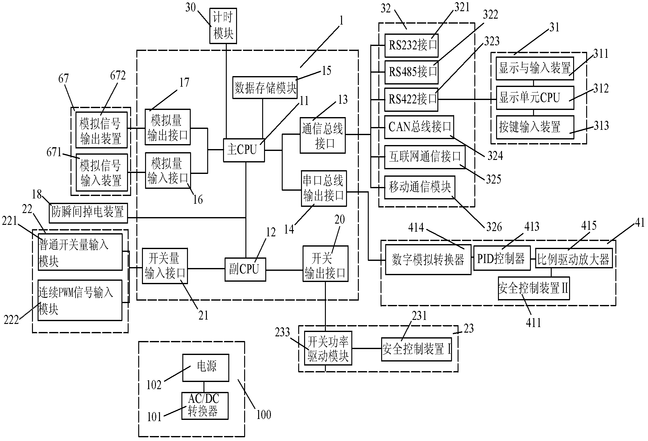
[0020] A hydraulic system integrated control device and control method are given, including a CPU unit 1, a power supply unit 100, a switch value and pulse input unit 22, a switch power drive unit 23, an analog signal input and output unit 67, a proportional drive unit 41, a communication unit 32 and interactive display unit 31.

[0021] The CPU unit 1 described above includes a main CPU11, a secondary CPU12, a communication bus interface 13, a serial bus output interface 14, a data storage module 15, an analog input interface 16, an analog output interface 17, a switch output interface 20, and a switch input Interface 21, anti-instantaneous power failure device 18 and timing module 30; Timing module 30, communication bus interface 13, serial port bus output interface 14, data storage module 15, analog quantity input interface 16 and analog quantity output interface 17 are all connected with main CPU11 Connection, both the switch value output interface 20 and the switch value ...


PUM


Abstract

The invention discloses an integrated control device and a control method for a hydraulic system. The integrated control device for the hydraulic system comprises a CPU (central processing unit), a power source unit, a switching and pulse input unit, a switch power drive unit, an analog signal input and output unit, a proportional driver unit, a communication unit and an interactive display unit. The switching and pulse input unit, the switch power drive unit, the analog signal input and output unit, the proportional driver unit, the communication unit and the interactive display unit are all connected with the CPU. The CPU, the switching and pulse input unit, the switch power drive unit, the analog signal input and output unit, the proportional driver unit, the communication unit and the interactive display unit are all connected with the power source unit and powered by the power source unit.

Description

technical field [0001] The invention relates to the hydraulic field, control technology and integrated circuit field, in particular to a hydraulic system integrated control device and control method. technical background [0002] The current hydraulic system control in industrial applications is mainly controlled by the combination of PLC, relay and proportional amplifier board. The PLC output signal controls the relay output switch signal, and the proportional amplifier board outputs proportional signal to drive the electromagnet. The entire electrical control system is based on the control cabinet and The installation of the console, if real-time monitoring of the operating status of the hydraulic system is required, it is necessary to install a computer and compile monitoring software. This type of control system is relatively complicated, and the volume is large, the cost is high, the connection is complicated, and maintenance is difficult. It is not suitable for applica...

Claims


Application Information

Patent Timeline
Patent Type & Authority Applications(China)
IPC IPC(8): G05D9/12
Inventor 王庆丰高达辉唐建中
Owner ZHEJIANG UNIV
Why Eureka
Try Eureka