
Magnetic tile adhering clamp for direct-current motor

A technology of DC motor and magnetic tile is applied in the field of fixture for magnetic tile bonding of DC motor, which can solve the problems of difficult bonding of magnetic tiles and incomplete positioning of magnetic tiles, so as to increase length and dimension, ensure positioning accuracy, and reduce The effect of manufacturing cost

Inactive Publication Date: 2012-09-19
宁波市北仑恒峰电机制造有限公司
View PDF6 Cites 2 Cited by
  • Summary
  • Abstract
  • Description
  • Claims
  • Application Information

AI Technical Summary

Problems solved by technology

[0003] The purpose of the present invention is to solve the problem that the magnetic tiles cannot be completely positioned in the magnetic tile bonding jig of the prior art, thereby making it difficult to bond the magnetic tiles, and to provide a method that can make the magnetic tiles in a state of reliable positioning. Adhesive and easy-to-manufacture DC motor magnetic tile bonding fixture, so as to facilitate the bonding of magnetic tiles and improve the size and position accuracy of magnetic tiles during bonding

Method used


Image

  • Magnetic tile adhering clamp for direct-current motor
  • Magnetic tile adhering clamp for direct-current motor
  • Magnetic tile adhering clamp for direct-current motor

Examples


Embodiment Construction

[0019] The present invention will be further described below in conjunction with the accompanying drawings and specific embodiments.

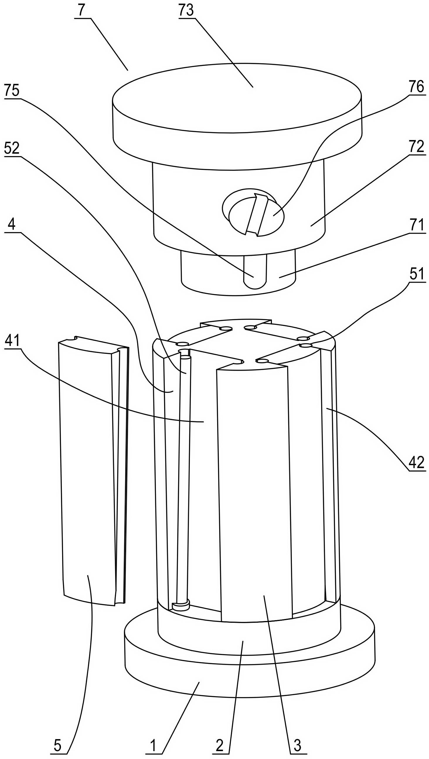
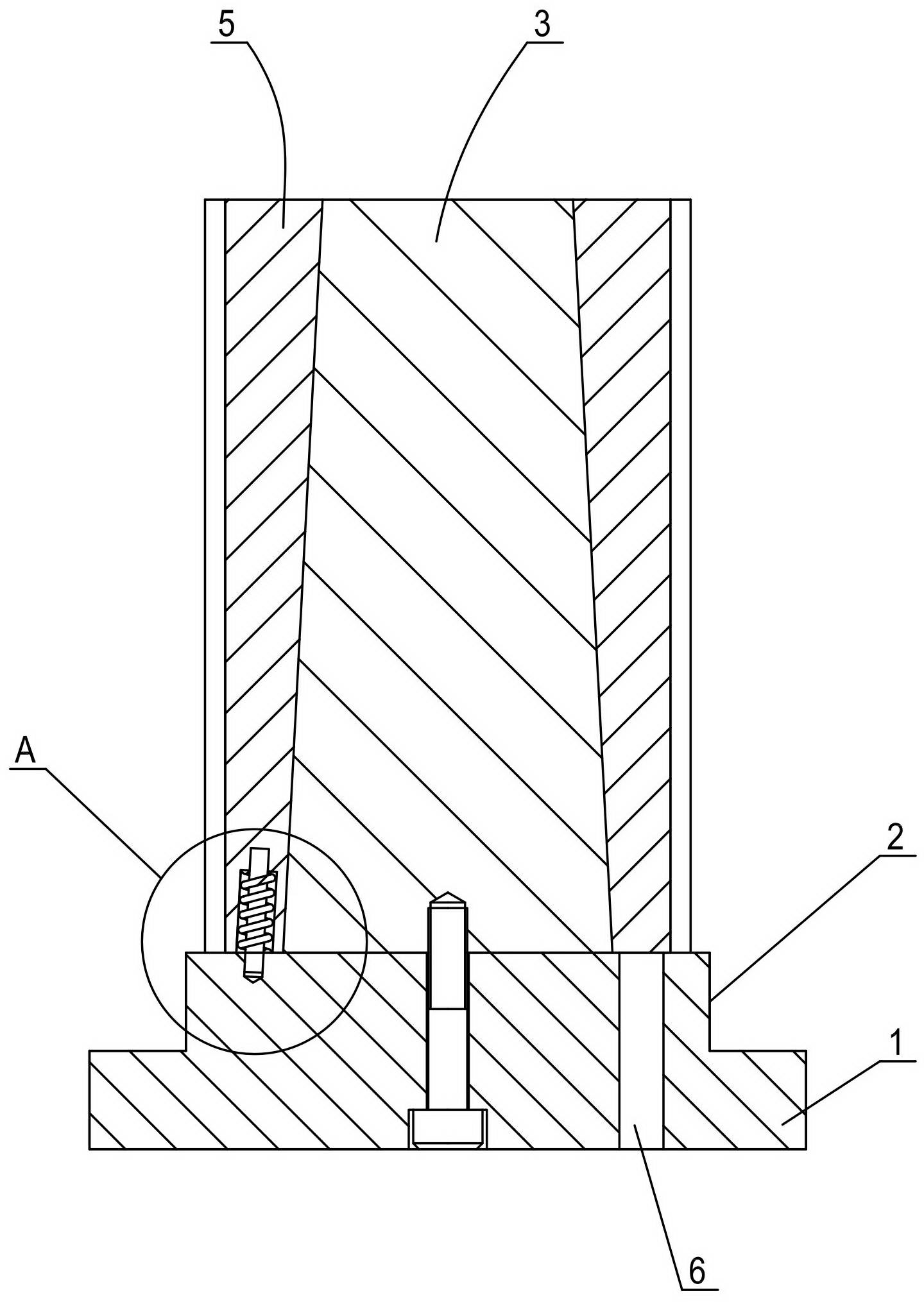
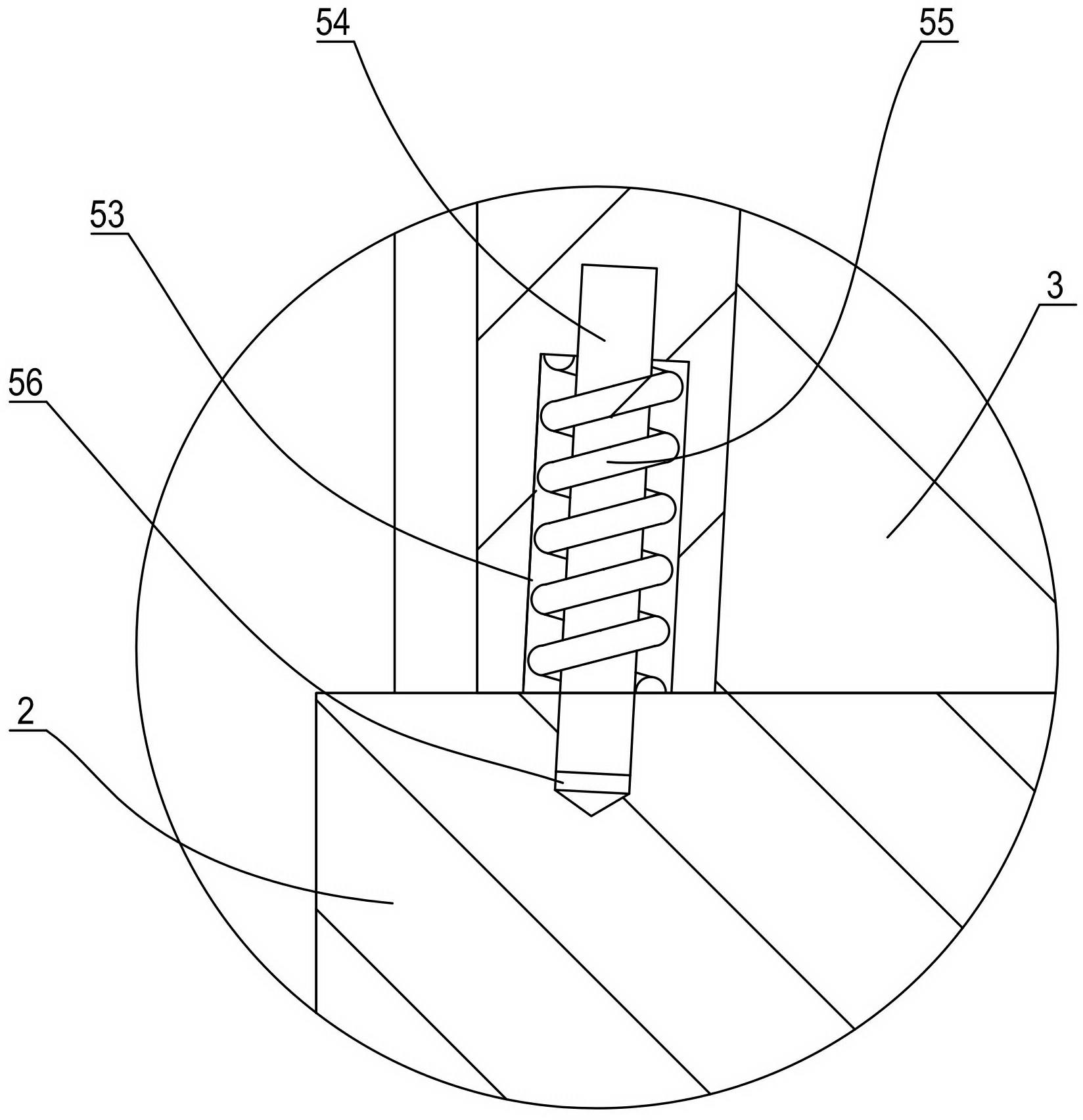
[0020] like figure 1 In the shown embodiment, a magnetic tile bonding fixture for a DC motor includes a disc-shaped base 1, a cylindrical pad 2 formed integrally on the upper surface of the base, and the diameter of the pad is the same as that of the DC motor casing The inner diameter of the fuselage is compatible, and the height of the heightening column can be determined according to the position of the magnetic tile on the fuselage of the DC motor casing. A positioning cylinder 3 with a split structure is provided on the upper surface of the heightening column, which is the same as the heightening column. The outer diameter of the positioning cylinder is also compatible with the inner diameter of the DC motor body, and the height of the positioning cylinder is comparable to that of the magnetic tile after splicing. The total length is 5 to ...


PUM


Abstract

The invention discloses a magnetic tile adhering clamp for a direct-current motor. The magnetic tile adhering clamp comprises a base, and an elevated column with the diameter matched with the inner diameter of a body of the direct-current motor is arranged on the upper surface of the base. The elevated column is provided with a positioning cylinder which is of a split structure, the outer diameter of the positioning cylinder is matched with the inner diameter of the body of the direct-current motor, an even number of U-shaped through grooves extending from the position of the upper end face to one side of the positioning cylinder are equally arranged on the outer side face of the positioning cylinder, sliding blocks are arranged in the U-shaped through grooves, sliding guiding structures are arranged between the sliding blocks and the U-shaped through grooves, the outer side faces of the sliding blocks are cambered surfaces matched with the inner side faces of magnetic tiles, the outer side face of each sliding block and the left side face and the right side face of each U-shaped through groove jointly form one magnetic tile positioning groove, and the inner side bottom surfaces of the U-shaped through grooves attached to the sliding blocks are locking slopes inclined outwards from top to bottom. The magnetic tile adhering clamp can guarantee positioning accuracy of the magnetic tiles in adhesion, and is favorable for increasing length dimensions of the magnetic tiles through splicing structures so as to manufacture the direct-current motor with large torque. The guiding structures of the clamp are simplified, thereby being favorable for reduction of manufacturing cost.

Description

technical field [0001] The invention relates to the field of DC motor manufacturing, in particular to a fixture used for bonding magnetic tiles of the DC motor. Background technique [0002] Due to the advantages of convenience, environmental protection and low price, electric bicycles are rapidly popularized in the market, so higher requirements are put forward for the DC motors used in electric bicycles, which need to have the performance of low speed and high torque, so that the vehicle It has good startup acceleration performance. The structure of the permanent magnet DC motor in the prior art generally includes a casing, a magnetic tile, a rotor, a commutator, etc., wherein the magnetic tile adopts a one-piece structure. To increase the torque of the DC motor, especially the starting torque, it is necessary to manufacture longer magnetic tiles. However, due to the limitations of the material characteristics of the magnetic tiles and the existing magnetic tile processi...

Claims


Application Information

Patent Timeline
Patent Type & Authority Applications(China)
IPC IPC(8): H02K15/00H02K15/03
Inventor 翁雪峰
Owner 宁波市北仑恒峰电机制造有限公司
Learn More