Video optical transmitter and receiver and detecting method for video optical transmitter and receiver

An optical transceiver and video technology, applied in the field of optical transmission, can solve the problems of increasing maintenance costs and affecting the use of video optical transceivers, and achieve the effect of saving maintenance costs

Active Publication Date: 2012-09-19
CHENGDU YINGDESI NETWORK TECH
View PDF6 Cites 2 Cited by
  • Summary
  • Abstract
  • Description
  • Claims
  • Application Information

AI Technical Summary

Problems solved by technology

[0004] In view of this, the present invention provides a video optical transceiver and a video optical transceiver detection method to solve any problems in the use or maintenance process of the prior art, which requires professional technicians to use professional testing equipment to detect and maintain on-site, or professional technicians The personnel dismantle the equipment that they think is faulty and send it back to the original factory for inspection to confirm the faulty optical transceiver, which will affect the use of the video optical transceiver and increase the maintenance cost

Method used


Image

  • Video optical transmitter and receiver and detecting method for video optical transmitter and receiver
  • Video optical transmitter and receiver and detecting method for video optical transmitter and receiver
  • Video optical transmitter and receiver and detecting method for video optical transmitter and receiver

Examples


Embodiment 1

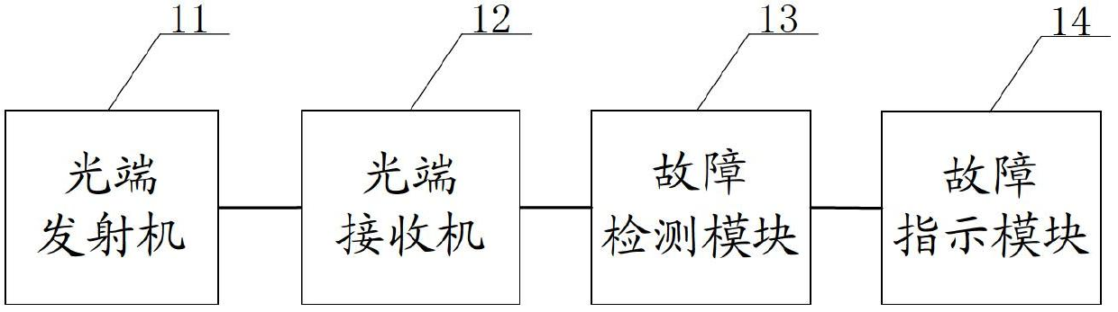
[0042] Embodiment 1 of the present invention provides a video optical transceiver, figure 1 Referring to the structural diagram of the video optical transceiver, the video optical transceiver provided by Embodiment 1 of the present invention includes: an optical transmitter 11 , an optical receiver 12 , a fault detection module 13 and a fault indication module 14 .

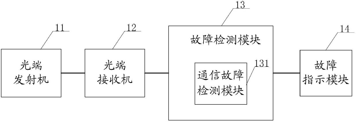
[0043] Wherein, the fault detection module 13 includes: a communication fault detection module 131, such as figure 2 As shown, the communication fault detection module 131 is used to detect whether the video optical transceiver where the fault detection module 13 is located and whether it communicates normally with the previous video optical transceiver connected to the video optical transceiver, when the video optical transceiver where the fault detection module 13 is located and is connected with When the communication between the last video optical transceiver connected to the video optical transceiver is abno...

Embodiment 2

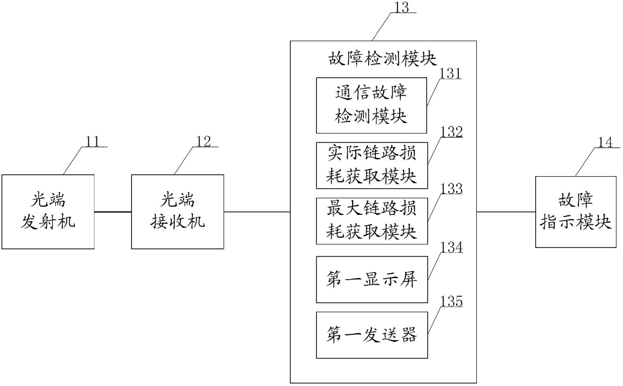
[0049] Embodiment 2 of the present invention provides a video optical transceiver, image 3 The structure schematic diagram of the video optical transceiver, the video optical transceiver provided by Embodiment 2 of the present invention includes: an optical transmitter 11 , an optical receiver 12 , a fault detection module 13 and a fault indication module 14 .

[0050] Different from the first embodiment, the fault detection module 13 in the second embodiment includes: in addition to the communication fault detection module 131, it also includes: the actual link loss acquisition module 132, the maximum link loss acquisition module 133 and the first display screen 134.

[0051] Among them, the actual link loss acquisition module 132 is used to acquire the optical power actually received by the optical receiver 12 of the video optical transceiver where the fault detection module 13 is located, and obtain the fault according to the received optical power and the preset transmitt...

Embodiment 3

[0058] Embodiment 3 of the present invention provides a video optical transceiver, Figure 4 This is a schematic structural diagram of the video optical transceiver. The video optical transceiver provided by Embodiment 3 of the present invention includes: an optical transmitter 11 , an optical receiver 12 , a fault detection module 13 and a fault indication module 14 .

[0059] Different from the second embodiment, the fault detection module 13 in the third embodiment includes: a communication fault detection module 131, an actual link loss acquisition module 132, a maximum link loss acquisition module 133, a first display screen 134 and a second In addition to a transmitter 135 , it also includes: a status monitoring module 136 and a second display screen 137 .

[0060] Wherein, the status monitoring module 136 is used to monitor the working status of the video optical transceiver where the fault detection module 13 is located, and when the monitoring detects that the video o...


PUM


Abstract

The invention provides a video optical transmitter and receiver which comprises an optical transmitter, an optical receiver, a fault indicating module and a fault detecting module, wherein the fault detecting module comprises a communication fault detecting module; the communication fault detecting module is used for detecting if the video optical transmitter and receiver, to which the fault detecting module belongs, and the last video optical transmitter and receiver connected with the video optical transmitter and receiver are normally communicated; and when the video optical transmitter and receiver and the last video optical transmitter and receiver connected with the video optical transmitter and receiver are abnormally communicated, the fault indicating module is controlled to indicate the fault. The video optical transmitter and receiver in fault is detected by the fault detecting module in the video optical transmitter and receiver provided by the invention. No professional technician is required for detecting and maintaining on the site by using special test equipment or disassembling the equipment which is confirmed as being problematic by the professional technician and sending to a manufacturer for detecting, so that the fault is timely eliminated, the influence on the use of the video optical transmitter and receiver is avoided while the maintenance cost is saved.

Description

technical field [0001] The present application relates to the field of optical transmission technology, and in particular to a video optical transceiver and a detection method for a video optical transceiver. Background technique [0002] Video optical transceivers used for uncompressed long-distance transmission of images in the video image monitoring industry have experienced two generations of development. The first generation is an analog video optical transceiver based on FM (Frequency Modulation, frequency modulation) technology, and the second generation is based on A digital video optical transceiver based on video digitization and non-compression time-division multiplexing technology. The digital video optical transceiver solves the shortcomings of analog video optical transceivers such as low transmission capacity, low business capability, easy signal attenuation, easy crosstalk, and poor product consistency. [0003] However, once any problem occurs during the us...

Claims


Application Information

Patent Timeline
Patent Type & Authority Applications(China)
IPC IPC(8): H04N7/22H04N17/00H04N17/04
Inventor 刘明学廖国刚
Owner CHENGDU YINGDESI NETWORK TECH
Why Eureka
Try Eureka