Stent delivery system

A delivery system and abutting part technology, applied in stents, medical science, prostheses, etc., can solve problems such as difficulties in stent storage operations, and achieve good results in release operations

Active Publication Date: 2012-09-19
TERUMO KK
View PDF12 Cites 10 Cited by
  • Summary
  • Abstract
  • Description
  • Claims
  • Application Information

AI Technical Summary

Problems solved by technology

In addition, in the stent delivery system of Patent Document 2, it is necessary to align the space between the stent supports with each protrusion, and it is difficult to accommodate the stent.

Method used


Image

  • Stent delivery system
  • Stent delivery system
  • Stent delivery system

Examples


Embodiment Construction

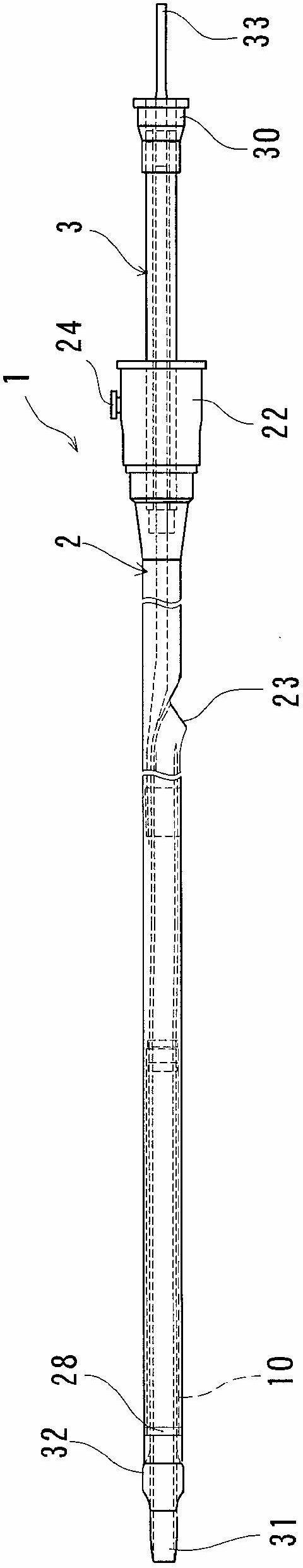
[0053] The stent delivery system of the present invention will be described using the embodiments shown in the drawings.

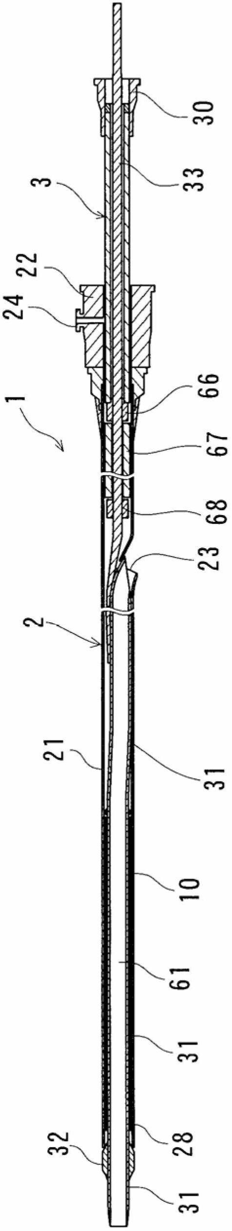
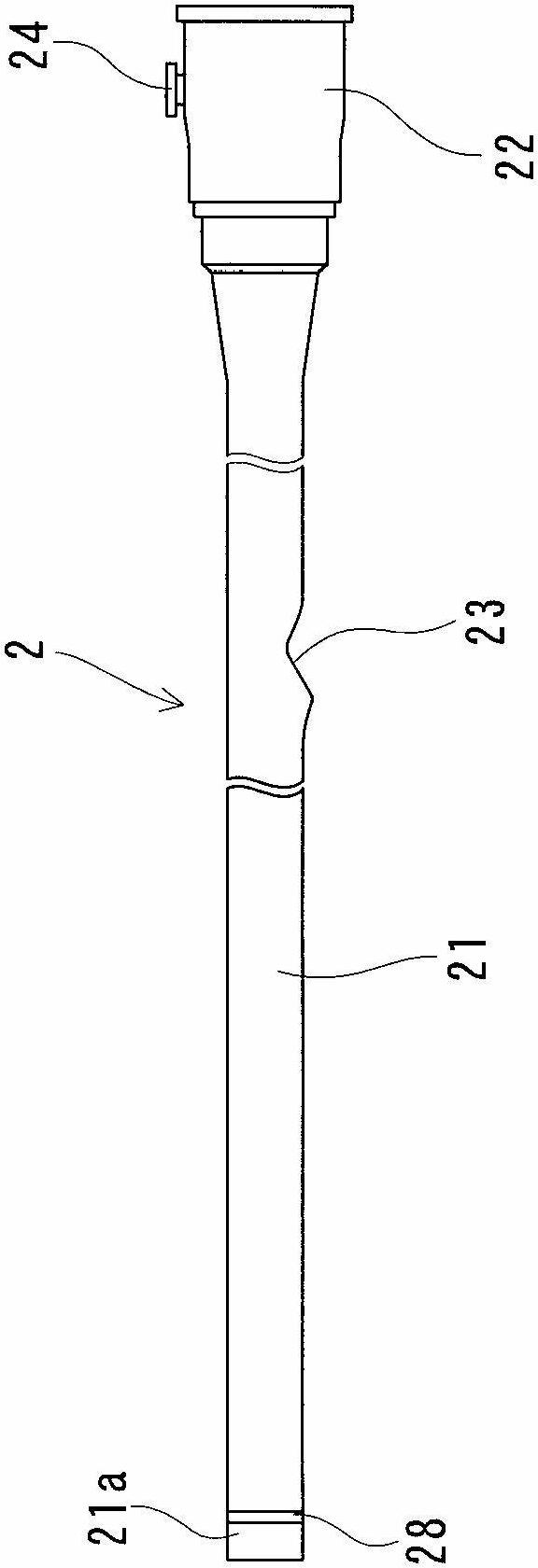
[0054] The stent delivery system 1 of the present invention (in other words, the device for improving the lesion of the organ of the living body) 1 includes: a stent 10 having a plurality of side wall openings, formed in a substantially cylindrical shape, and being inserted in the direction of the central axis when inserted into the living body. Compression, when left in the living body, it can expand outward and return to the shape before compression; the inner tube (rod) 3 has a guide wire lumen 61; the stent receiving tube (outer jacket) 2, which holds the 10 is accommodated in the distal end; and the stent 10 can be released by disposing the stent 10 covering the distal end of the inner tubular body 3 and moving the stent accommodating tubular body 2 to the proximal side relative to the inner tubular body 3 .

[0055] Moreover, the inner tubular body 3...


PUM


Abstract

A stent delivery system (1) includes a self-expanding stent (10), an inner tube body (3), and a sheath (2) which contains the stent (10) within a distal portion thereof. The stent (10) can be discharged by moving the sheath (2) toward the proximal side relative to the inner tube body (3). The inner tube body (3) includes: a distal contact section (36) which is provided within a proximal portion of the stent (10) and does not enter side wall openings of the stent; and a proximal contact section (35) which is located at a position rear of the proximal end of the stent (10) and close to the distal contact section (36). The stent (10) has a proximal inwardly protruding section (17a) which can make contact with the distal contact section (36) of the inner tube body (3). The proximal inwardly protruding section is located between the distal contact section (36) and the proximal contact section (35). The stent (10) does not, except in the proximal portion thereof, have a bend free end which protrudes to the proximal side.

Description

technical field [0001] The present invention relates to a stent delivery system for improving the generation of stenosis or occlusion in blood vessels, bile ducts, trachea, esophagus, urethra and other living body lumens. Background technique [0002] The stent delivery system includes a stent for ameliorating a stenosis or an occlusion. A stent is a usually tubular medical device that is placed in the stenosis or occlusion in order to treat various diseases caused by the stenosis or occlusion of blood vessels or other biological lumens, and to ensure the lumen of the site. utensils. [0003] In the following, a blood vessel is taken as an example for description, but it is not limited thereto. [0004] The stent has a small diameter at the time of insertion in order to be inserted from the outside of the body into the body, expands to increase the diameter at the target narrowed site or occluded site, and directly maintains the lumen of the site. [0005] The bracket is ...

Claims


Application Information

Patent Timeline
Patent Type & Authority Applications(China)
IPC IPC(8): A61F2/84A61F2/91A61F2/915A61F2/95A61F2/966
CPCA61F2/966A61F2230/0054A61F2/915A61F2002/9505A61F2/91A61F2/95
Inventor 杉本良太北冈孝史
Owner TERUMO KK
Why Eureka
Try Eureka