Through-flow fan, air blower, and air conditioner
A technology of cross-flow fans and air passages, applied in the field of cross-flow fans, can solve the problems of increasing length and the influence of fan power consumption and air supply performance, and achieve uniform distribution of wind speed, low noise, and low input. Effect
- Summary
- Abstract
- Description
- Claims
- Application Information
AI Technical Summary
Problems solved by technology
Method used
Image
Examples
Embodiment approach 1
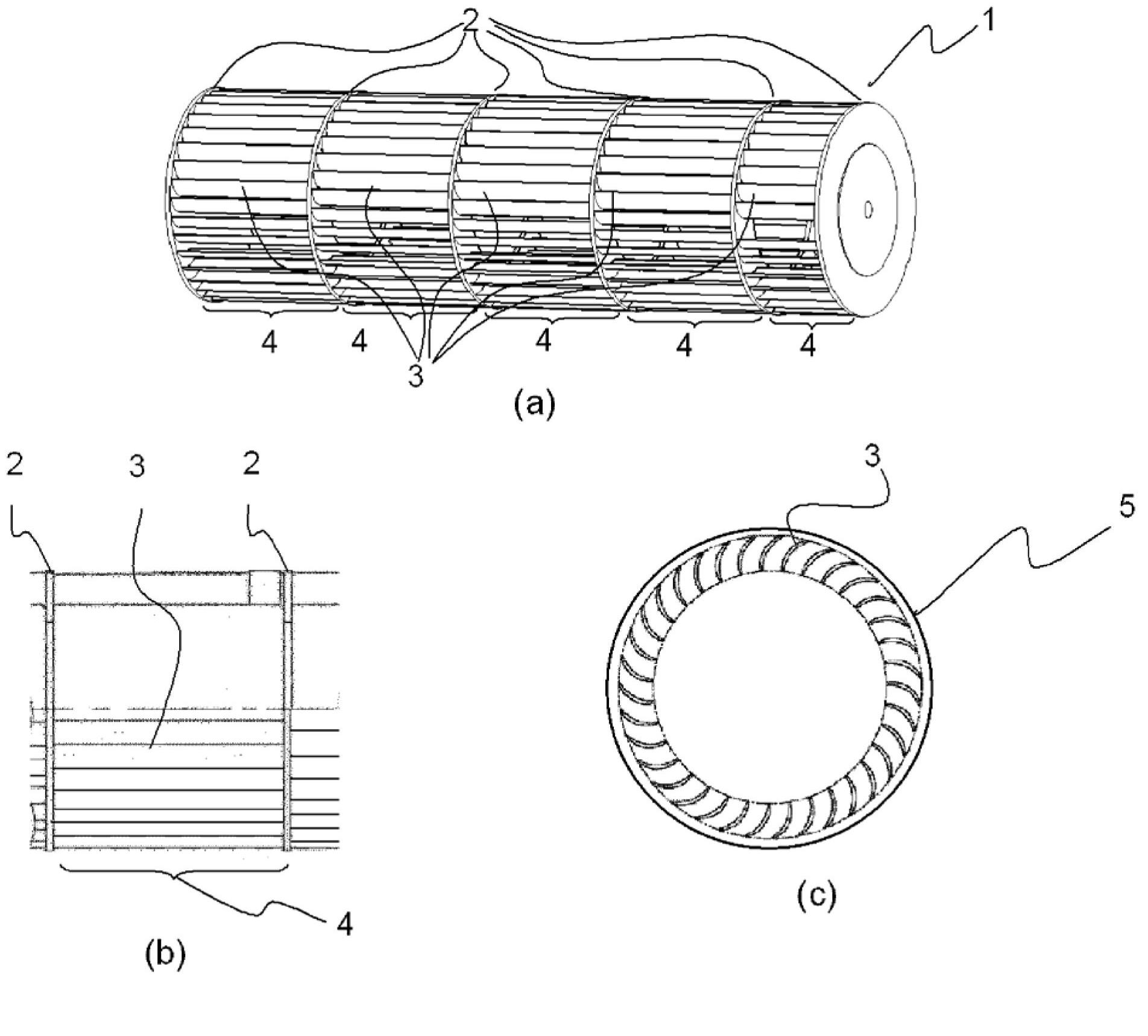
[0058] figure 1 (a) is a perspective view showing the appearance of cross-flow fan 1 according to Embodiment 1 of the present invention. A plurality of blades 3 supported at both ends by the ring 2 are attached in the circumferential direction of the ring 2 . A plurality of impeller units 4 (hereinafter, referred to as one unit) composed of the ring 2 and the blades 3 are connected in the axial direction of the fan, thereby constituting the cross-flow fan 1 . figure 1 (b) is a front view of main parts of the impeller unit 4 . like figure 1 As shown in (b), the outer diameter formed by the outer edge portion of the blade 3 is constant in the axial direction of the cross-flow fan 1 . figure 1 (c) is a figure which shows the longitudinal section of the impeller of one unit. The ring outer diameter 5 is larger than the outer diameter of the vanes 3 , and the vanes 3 are radially engaged and fixed to the ring 2 at positions inside the outer circumference of the ring 2 . In add...
Embodiment approach 2
[0077] In Embodiment 1, the increase or decrease of the blown air volume is changed by the curvature of the blades, and the air volume may be changed by the chord length of the blades below.
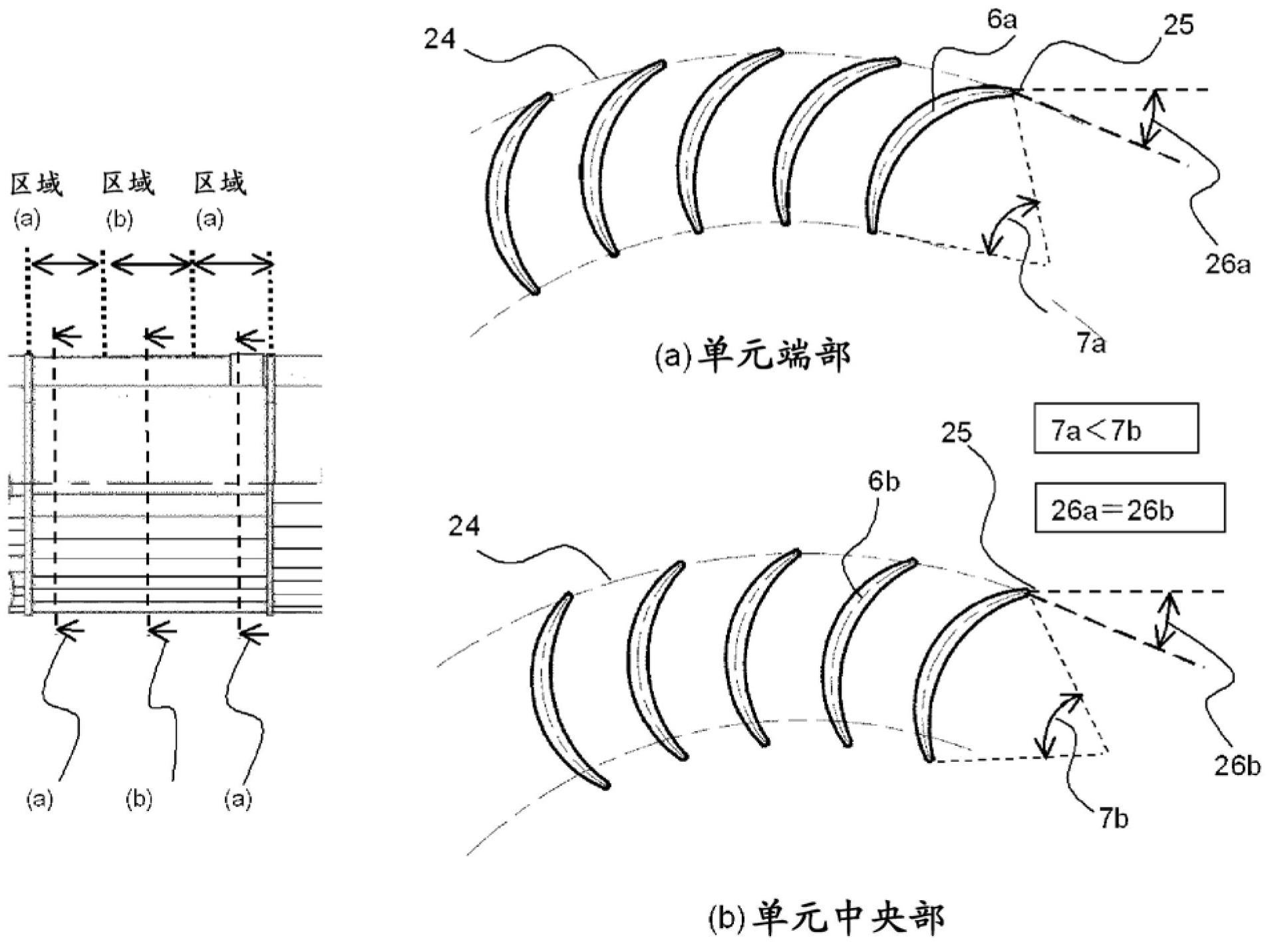
[0078] Figure 5 It is a vertical cross-sectional view of the cross-flow fan 1 according to the second embodiment. As in Embodiment 1, the impeller cross section of one unit is divided into a unit end portion (a) and a unit center portion (b) and shown. Focusing on the cross-section of the blade, it is characterized in that the blade chord length 23b at the center of the unit is longer than the blade chord length 23a at the end of the unit with respect to the straight line (blade chord length 23) connecting the front end of the blade and the rear end of the blade (23a<23b) .
[0079] In addition, similar to Embodiment 1, in the cross section of the blade, the exit angle 26a (or 26b) at the intersection point 25 where the blade centerline 6a (or 6b) intersects the arc 24 of the blade ou...
Embodiment approach 3
[0086] The configurations shown so far are examples in which the shape of the blades varies in the width direction between one impeller unit. When the shape of the blade is changed in the width direction, if the change is sudden, a step difference may be generated on the blade surface, eddy current may be generated on the surface, pressure fluctuation may be increased, and noise may be deteriorated.
[0087] Figure 6 (A) is a front view of the cross-flow fan of Embodiment 3, Figure 6 (B) is Figure 6 (A) Perspective view of cross-flow fan in region (ab) part. In Embodiment 3, a region (ab) is provided in which a continuous inclined surface is formed between the region (a) and the region (b) of the impeller, whereby between the region (a) and the region (b), the The mode changes smoothly without causing a step difference on the blade surface.
[0088] According to Embodiment 3, since the step difference on the surface of the blade disappears, there is an effect that gener...
PUM
 Abstract
Description
Claims
Application Information
 - R&D
- Intellectual Property
- Life Sciences
- Materials
- Tech Scout
- Unparalleled Data Quality
- Higher Quality Content
- 60% Fewer Hallucinations
Browse by: Latest US Patents, China's latest patents, Technical Efficacy Thesaurus, Application Domain, Technology Topic, Popular Technical Reports.
© 2025 PatSnap. All rights reserved.Legal|Privacy policy|Modern Slavery Act Transparency Statement|Sitemap|About US| Contact US: help@patsnap.com


