Sanitary outlet unit

A sanitation and discharge port technology, applied in the direction of engine components, ventilation devices, multi-way valves, etc., can solve the problems of incompletely overcome, sealing, etc., and achieve the effect of simple formation and effective control

Active Publication Date: 2012-09-19
NEOPERL
View PDF9 Cites 0 Cited by
  • Summary
  • Abstract
  • Description
  • Claims
  • Application Information

AI Technical Summary

Problems solved by technology

Furthermore, in the water valves involved, sealing problems can arise on the diaphragm and on the valve, espec...

Method used


Image

  • Sanitary outlet unit
  • Sanitary outlet unit
  • Sanitary outlet unit

Examples


Embodiment Construction

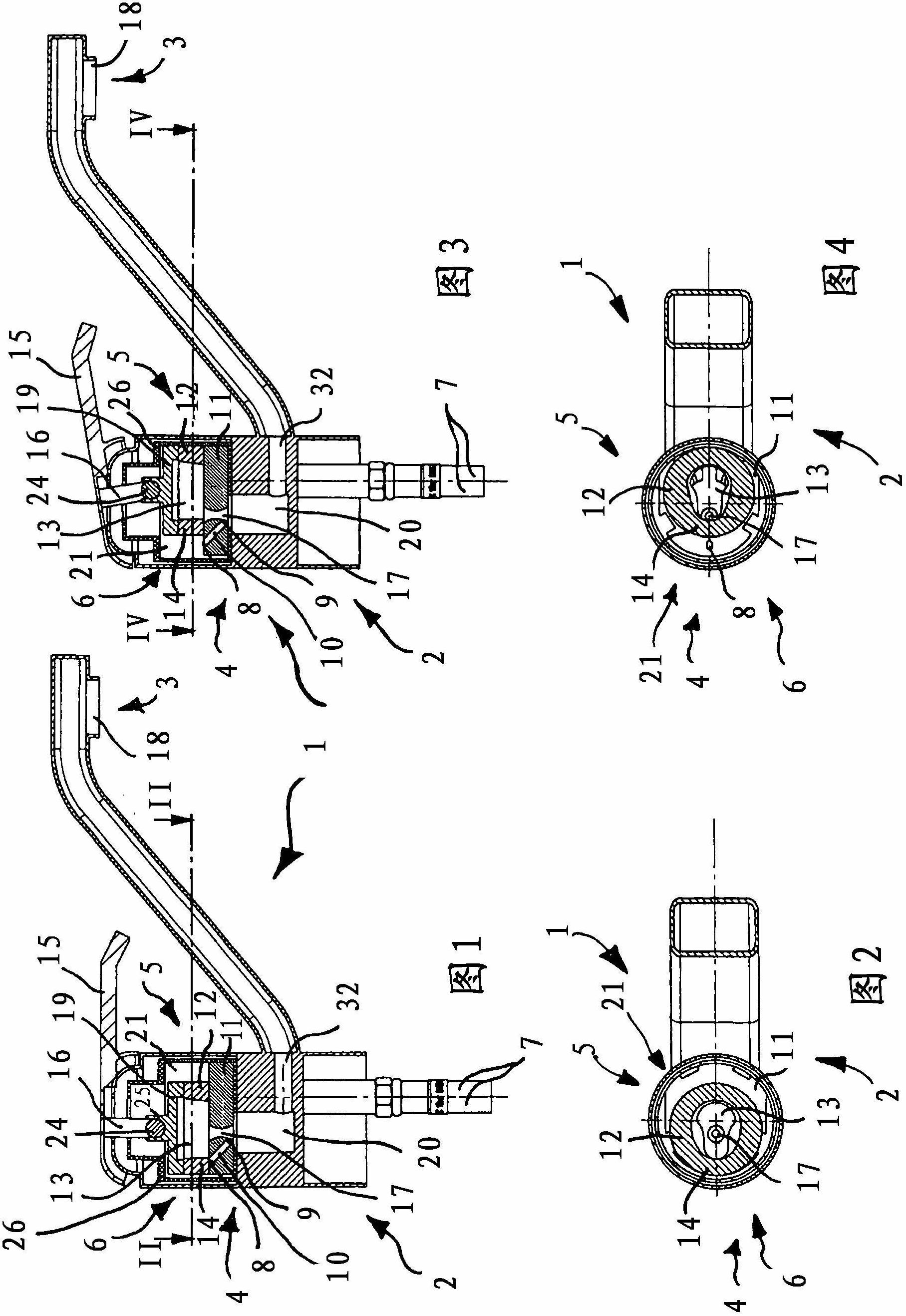
[0035] exist Figures 1 to 4 In the figure, a sanitary discharge unit with a water valve 2 can firstly be seen as a whole, which has a water outlet 3 which, due to the section along II-II and IV-IV, is not in the figure 2 and 4 shown in . as from figure 1 and 3 It can be seen from the figure that the inflow of water can be supplied to the valve member 5 through the water pipe 7, and the outflow of water from the water outlet can be adjusted through the valve member 5. To aerate the water jets, an aeration device 4 is arranged on the discharge unit 1 , which is located at a distance in the direction of flow in front of the discharge of the water outlet 3 .

[0036] as in figure 1 and 3 As seen in , the filling device 4 of the discharge unit 1 is received in the valve member 5 and is provided with an actuator 6 whose movement between an open position and a closed position changes the flow of ambient air to the interior of the valve member 5 Supply in the water jet. In t...


PUM


Abstract

The invention relates to a sanitary outlet unit (1) comprising an outlet fitting (2) having at least one water outlet (3) and comprising an aeration device (4) provided for aerating the water flow and arranged in the flow direction spaced from and upstream of the at least one water outlet (3), and comprising at least one valve part (5), which regulates the inflow from at least one water pipe (7) to the water outlet (3). In order to provide a sanitary outlet unit (1) that ensures reliable aeration of the water flow combined with good water tightness to water running back and that can be integrated without undue structural modifications into existing fittings, according to the invention the aeration device (4) is received in the at least one valve part (5) and the aeration device (4) is provided with at least one actuator (6), the movement of which between at least one closed and at least one open position alters the admission of ambient air to the water flow inside the valve part (5).

Description

technical field [0001] The invention relates to a hygienic discharge unit having a water valve with at least one water outlet, at least one aeration device for aerating a water jet, and at least one valve element, the aeration device along a flow Directly spaced apart in front of the at least one water outlet, the valve member regulates inflow from the at least one water pipe to the water outlet. Background technique [0002] Discharge units are already known, in which a water jet regulator is arranged in the area of ​​the water outlet, which is intended to aerate the water jet emerging from the water outlet and form a uniform, bead-like soft water jet. bundle. For this purpose, known water jet regulators have, in their water jet regulator housing, water jet splitters, mostly designed as perforated plates, downstream of which a homogenizing device and possibly a rectifier are connected. The water jet regulator housing of the known water jet regulator has gas filling openin...

Claims


Application Information

Patent Timeline
IPC IPC(8): F16K11/06
CPCF16K24/02F16K11/0787
Inventor H・许尔勒W・巴默林M・施泰因布伦纳
Owner NEOPERL
Why Eureka
Try Eureka