Planet bearing lubricating device in gear box

A technology for bearing lubrication and planetary bearings, which is applied in gear lubrication/cooling, transmission parts, belts/chains/gears, etc. It can solve problems such as difficulty in determining the amount of oil supplied to lubrication points, loss of oil pressure along the way, and complex oil passages.

Inactive Publication Date: 2012-09-26
ZHEJIANG TONGLI HEAVY GEAR
View PDF5 Cites 5 Cited by
  • Summary
  • Abstract
  • Description
  • Claims
  • Application Information

AI Technical Summary

Problems solved by technology

[0002] In the prior art, there are mainly two types of planetary structure bearing lubrication: forced oil supply and non-forced oil supply. The problems of forced lubrication are: complex oil passage, serious loss of oil pressure along the way, complicated calculation, oil loss during oil supply, It is difficult to determine the actual lubrication point oil supply
At present, non-forced lubrication mainly adopts oil immersion, splashing, oil collecting pan, etc. The problem of the oil immersion method is that the rotating parts of the planetary structure, especially the planetary wheel, can only be submerged for a short time; the problem of the splash method is that the amount of splashed oil is not sufficient. control, unable to enter the planetary bearing lubrication; the problem of the oil collecting pan is that the opening of the oil collecting pan is very small due to the space limitation, and the oil that can be splashed into the pan during one revolution is extremely limited, and the lubricating oil has no pressure Cannot effectively reach the lubrication point

Method used


Image

  • Planet bearing lubricating device in gear box
  • Planet bearing lubricating device in gear box
  • Planet bearing lubricating device in gear box

Examples


Embodiment Construction

[0020] The present invention will be described in further detail below in conjunction with the accompanying drawings and specific embodiments.

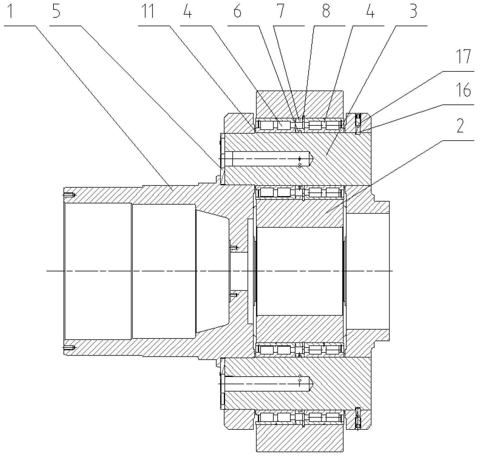
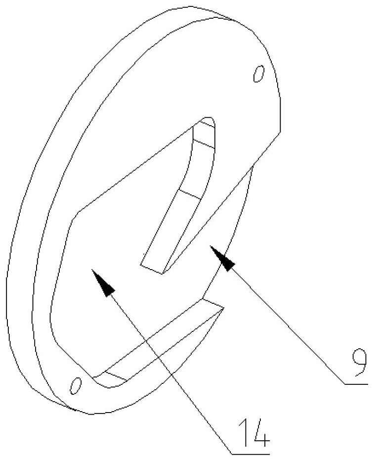
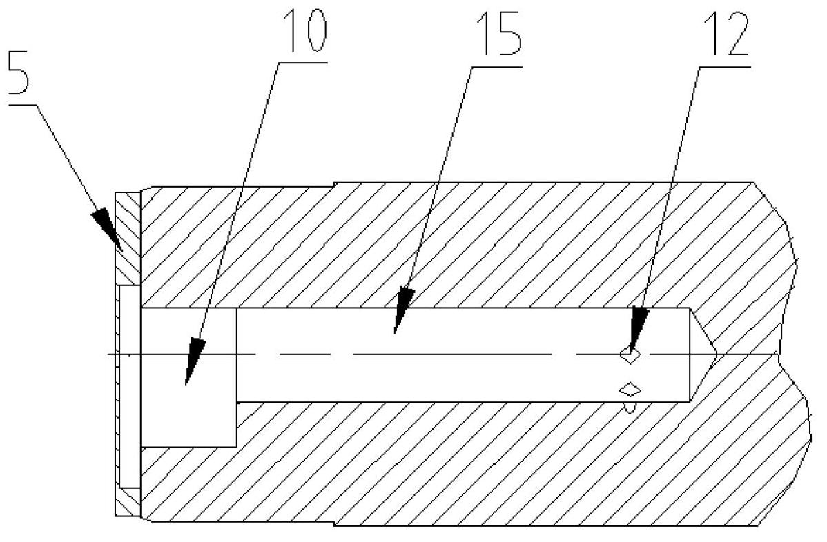
[0021] Such as Figure 1-3 As shown, the present invention provides a planetary bearing lubricating device in a gearbox, comprising a planetary carrier 1, a planetary wheel 2, a planetary shaft 3, a planetary bearing 4, an oil shoveling plate 5, a bearing inner ring spacer 6 and a bearing outer ring spacer ring 7, the planetary shaft 3 is fixedly installed on the planet carrier 1, and the planetary wheel 2 is installed on the planetary shaft 3 through the planetary bearing 4; the planetary bearing 4 is left and right, and the two planetary bearings 4 are separated by the inner ring of the bearing. The ring 6 is separated from the spacer 7 of the outer ring of the bearing; The oil shoveling plate 5 is fixedly installed on the end of the planetary shaft 1. The oil shoveling plate 5 includes an oil shoveling port 9 and an oil shoveling ...


PUM


Abstract

The invention provides a planet bearing lubricating device in a gear box, comprising a planet frame, a planet wheel, a planet shaft, a planet bearing, an oil shoveling plate, a bearing inner ring space ring and a bearing outer ring space ring, wherein the oil shoveling plate is mounted at the end part of the planet shaft; the oil shoveling plate is provided with an oil shoveling opening and an oil shoveling chamber; the planet shaft is internally provided with an oil storage chamber and an oil conveying hole; one end of the oil storage chamber is communicated with the oil shoveling chamber and the other end of the oil storage chamber is communicated with the oil conveying hole; an inner annular groove is arranged in the middle of the bearing inner ring space ring; and a plurality of oil supplying holes communicated with the annular grooves are arranged at the tail part of the oil conveying hole. According to the invention, with the adoption of a non-forced lubricating manner, the oil supplying amount can be reduced and the cost is greatly saved; the structure of the lubricating device is simple, the risk that the oil supply is insufficient due to the fact that oil supplying equipment is invalid is reduced, and the equipment reliability is greatly improved; and the lubricating device can be designed by adjusting the oil shoveling amount through the size of an oil shoveling region and the thickness of the oil shoveling plate; and the calculation is simple and the design difficulty is small.

Description

technical field [0001] The invention belongs to a lubricating device for a gear box, in particular to a planetary bearing lubricating device for a planetary gear box. Background technique [0002] In the prior art, there are mainly two types of planetary structure bearing lubrication: forced oil supply and non-forced oil supply. The problems of forced lubrication are: complex oil passage, serious loss of oil pressure along the way, complicated calculation, oil loss during oil supply, The actual amount of oil supplied to the lubrication point is difficult to determine. At present, non-forced lubrication mainly adopts oil immersion, splashing, oil collecting pan, etc. The problem of the oil immersion method is that the rotating parts of the planetary structure, especially the planetary wheel, can only be submerged for a short time; the problem of the splash method is that the amount of splashed oil is not sufficient. control, unable to enter the planetary bearing lubrication...

Claims


Application Information

Patent Timeline
Patent Type & Authority Applications(China)
IPC IPC(8): F16H57/04F16H57/08
CPCF16H57/0479
Inventor 王雄厚何芸陈斌叶爱雪项建忠陈永生
Owner ZHEJIANG TONGLI HEAVY GEAR
Why Eureka
Try Eureka