[0021] The present invention will be described in detail below in conjunction with the drawings:
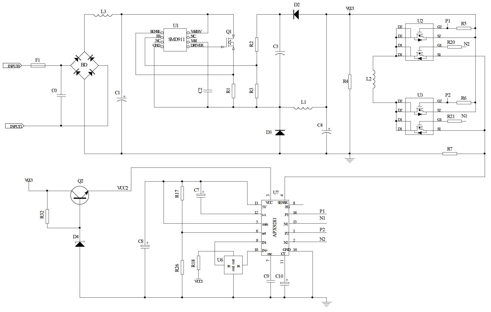
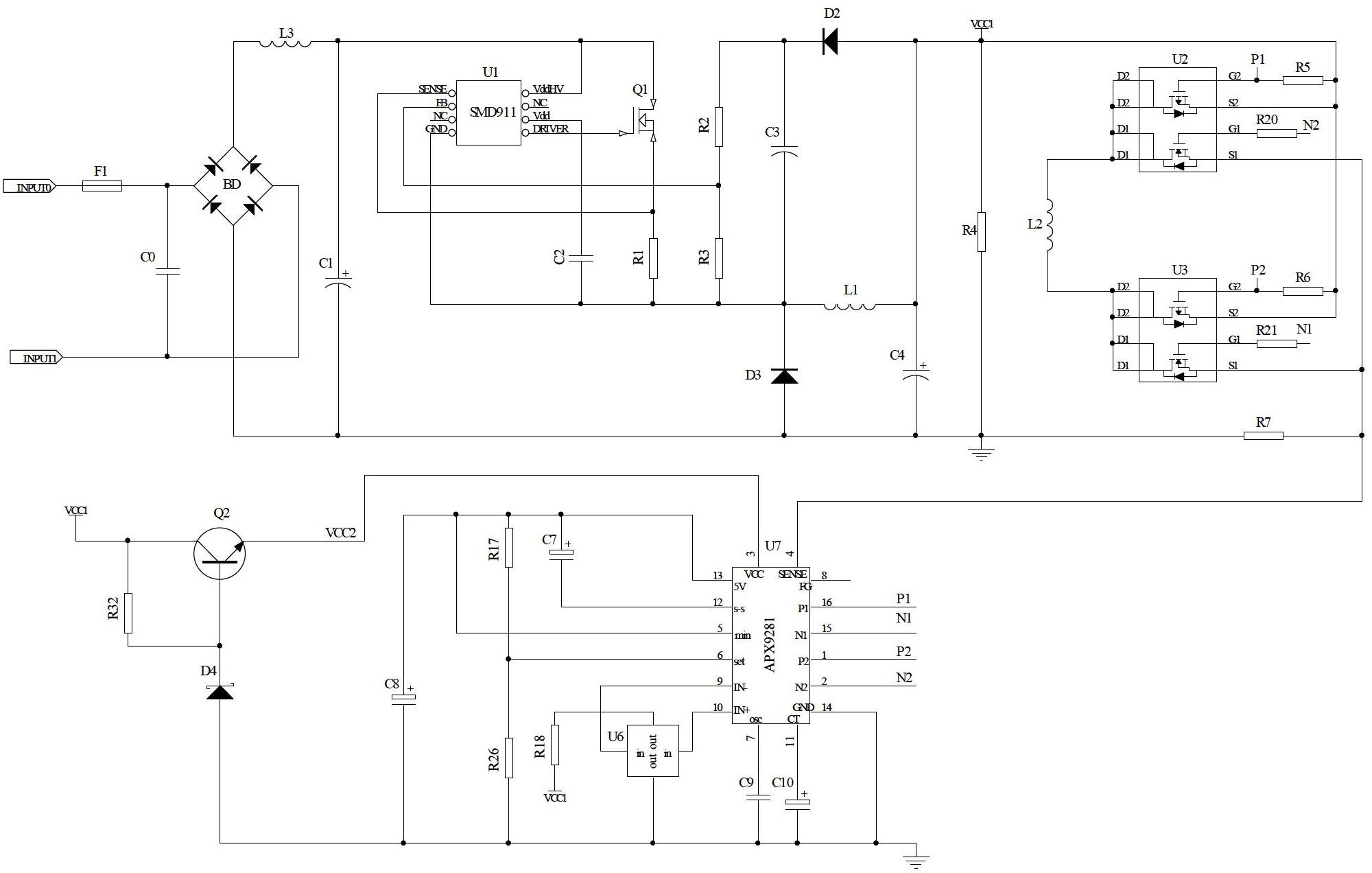
[0022] Please refer to figure 1 , The AC fan control circuit of the embodiment of the present invention includes a rectifier circuit, a filter circuit, an electromagnetic interference circuit, a DC-DC switch circuit, and a fan drive circuit.
[0023] Among them, the rectifier circuit is used to convert the AC power of the power grid into a pulsating DC power; the rectifier circuit in this embodiment adopts a rectifier bridge BD composed of four diodes, which may also be a rectifier bridge block.
[0024] Wherein, the filter circuit is arranged in the output stage of the rectifier circuit to filter out the harmonic voltage generated by the rectifier circuit. The filter circuit in this embodiment adopts an LC type filter circuit, including the output of the rectifier circuit connected in parallel. The first capacitor C1 of the stage, and the third inductor L3 serially connected to the output positive terminal of the rectifier circuit.
[0025] Wherein, the electromagnetic interference circuit is set in the input stage of the rectifier circuit to prevent electromagnetic interference with other circuits when the AC fan control circuit is working; the electromagnetic interference circuit in this embodiment is set in the rectifier circuit The zeroth capacitance C0 of the input stage.
[0026] Wherein, the DC-DC switch circuit is arranged in the output stage of the filter circuit, and is used to transform the higher pulsating DC power output from the rectification and filter circuit into a stable first DC power supply VCC1; including the model SMD911 The high-voltage switch-type regulator chip U1 and the switch tube Q1, the high-voltage pin (pin 8) of the high-voltage switch-type regulator chip U1 and the drain terminal of the switch tube Q1 are pulsating direct current output by the rectifier and filter circuit The power supply is provided. The driving pin (pin 5) of the high-voltage switching regulator chip U1 is connected to the gate terminal of the switching tube Q1, and the source terminal of the switching tube Q1 is output through the first resistor R1 and the first inductor L1 connected in series. The first DC power supply VCC1, the common intersection of the first resistor R1 and the first inductor L1 is connected to the ground pin (pin 4) of the high-voltage switching regulator chip U1, and the output terminal of the first inductor L1 Is the output terminal of the DC-DC switch circuit, a fourth capacitor C4 and a dummy load are connected in parallel between the output terminal of the DC-DC switch circuit and ground, and the dummy load is connected to the DC-DC switch A fourth resistor R4 between the output terminal of the circuit and the ground; a second capacitor C2 is connected between the power pin (pin 6) and the ground pin (pin 4) of the high-voltage switching regulator chip U1; A feedback circuit is connected between the output terminal of the DC-DC switch circuit and the feedback pin (pin 2) of the high-voltage switch-type voltage regulator chip U1, and the feedback circuit includes a circuit connected in series with the DC-DC switch circuit. The second diode D2, the second resistor R2 and the third resistor R3 between the output terminal and the ground pin (4th pin) of the high-voltage switch-type regulator chip U1, the second resistor R2 and the third resistor R2 The common intersection of the resistor R3 and the feedback pin (pin 2) of the high-voltage switching regulator chip U1 is connected to the detection pin (pin 1) of the high-voltage switching regulator chip U1 and the source of the switching tube Q1 Connected, a third diode D3 is connected inversely between the ground pin (pin 4) of the high-voltage switching regulator chip U1 and the ground.
[0027] Among them, the fan driving circuit is used to drive the fan to rotate forward or reverse; it includes a first dual-channel FET chip U2, a second dual-channel FET chip U3, and a driving coil L2 of the fan; the first dual-channel field The effect tube chip U2 and the second dual-channel FET chip U3 both include an N-channel first triode and a P-channel second triode, the model number is APM4588K; the first dual-channel field The common intersection point after all the drain pins D1 of the first triode of the effect tube chip U2 and all the drain pins D2 of the second triode are connected with the first triode of the second dual-channel FET chip U3 The common intersection point after all drain pins D1 and all drain pins D2 of the second triode are connected is connected to the driving coil L2, and the source pin of the second triode of the first dual-channel FET chip U2 S2 and the source pin S2 of the second triode of the second dual FET chip U3 are connected to the first DC power supply VCC1, and the first triode of the first dual FET chip U2 The source pin S1 of the tube and the source pin S1 of the first triode of the second dual-channel FET chip U3 are connected to the common intersection point through the seventh resistor R7; the first dual-channel FET is grounded; The gate pin G2 of the second triode of the chip U2 and the gate pin G2 of the second triode of the second dual-channel FET chip U3 are connected to the first through the fifth resistor R5 and the sixth resistor R6, respectively. DC power supply VCC1, and the gate pin G2 of the second triode of the first dual-channel FET chip U2 and the gate pin of the second triode of the second dual-channel FET chip U3 G2 is also connected to a second forward control signal P2 and a first forward control signal P1 respectively; the gate pin G1 of the first triode of the first dual-channel FET chip U2 and the second dual-channel The gate pin G1 of the first triode of the field effect transistor chip U3 is connected to the second reverse control signal N2 and the first reverse control signal N1 through the twentieth resistor R20 and the twenty-first resistor R21, respectively.
[0028] The above-mentioned first forward control signal P1, second forward control signal P2, first reverse control signal N1, and second reverse control signal N2 are all provided by the motor pre-driver chip U7; please refer to figure 1 The model of the motor pre-drive chip U7 is APX9281 or LB11867, the third pin of the motor pre-drive chip U7 is connected to the second DC power supply VCC2, the 14th pin is grounded, and the ninth pin is connected to the ground. Capacitor C9, the tenth capacitor C10 is connected between the 11th pin and the ground, the 13th pin outputs a 5V voltage, the eighth capacitor C8 is connected between the 13th pin and the ground, and the 13th pin and the 12th pin are connected The seventh capacitor C7, the 13th pin is connected to the 5th pin, and the 17th resistor R17 and the 26th resistor R26 are sequentially connected between the 13th pin and the ground, and the seventeenth resistor R17 and the twentieth The common intersection of the six resistors R26 is connected to the 6th pin of the motor pre-drive chip U7. The 9th and 10th pins of the motor pre-drive chip U7 are provided by the Hall element U6, and the two pins of the Hall element U6 The two input pins are respectively connected to the 9th and 10th pins of the motor pre-drive chip U7; one of the output pins of the Hall element U6 is grounded, and the other output pin of the Hall element U6 passes through the eighteenth pin. The resistor R18 is connected to the second DC power supply VCC2. The 16th pin and the 1st pin of the motor pre-drive chip U7 respectively output the first forward control signal P1 and the second forward control signal P2. The motor pre-drive chip U7 The 15th pin and the second pin respectively output the first reverse control signal N1 and the second reverse control signal N2.
[0029] When the motor pre-driving chip U7 outputs the first forward control signal P1 and the second reverse control signal N2, the first triode of the first dual-channel field effect transistor chip U2 is turned on, and the second The second triode of the dual FET chip U3 is turned on, and the driving coil L2 drives the fan to rotate forward; when the motor pre-driving chip U7 outputs the second forward control signal P2 and the first reverse control signal N1, The second triode of the first dual FET chip U2 is turned on, the first triode of the second dual FET chip U3 is turned on, and the driving coil L2 drives the fan to reverse.
[0030] In a more preferred embodiment, the second DC power supply VCC2 in this embodiment includes a second triode Q2, and the collector of the second triode Q2 is connected to the first DC power supply VCC1. The emitter of the second triode Q2 outputs a second DC power supply VCC2, a thirty-second resistor R32 is connected between the base and the collector of the second triode Q2, and the second triode Q2 A fourth diode D4 is reversely connected between the base and the ground, and the fourth diode D4 is a voltage regulator tube. The second DC power supply VCC2 in this embodiment adopts the second transistor Q2 and the thirty-second resistor R32 to form an emitter follower, so the cost is low.
[0031] As a preferred embodiment, the model of the Hall element U6 in this embodiment is HW101A.
[0032] In this embodiment, a fuse F1 is provided at the input stage of the rectifier circuit to protect it from overcurrent and overheating.
[0033] The AC fan control circuit of the present invention includes a rectifier circuit, a filter circuit, a DC-DC switch circuit, and a fan drive circuit. Among them, the DC-DC switching circuit is used to transform the higher pulsating DC power output from the rectification and filtering circuit into a stable first DC power VCC1. The circuit structure uses a high-voltage switch-type regulator chip U1 and a switch tube Q1, since the first DC power supply VCC1 output by the DC-DC switch circuit is directly supplied to the fan drive circuit, the power supply obtained by the drive coil L2 of the fan is more stable and reliable, so that the fan can rotate reliably and stably. In addition, the fan drive circuit uses two dual-channel FET chips and the fan drive coil L2 to form an H-bridge drive circuit, and the control signal in the H-bridge drive circuit is provided by the motor pre-drive chip U7. The working principle of the output control signal of the drive chip U7 can be seen that only one set of control signals is output at the same time, that is, either the first forward control signal P1 and the second reverse control signal N2 are output; or the second forward control signal P2 and The first reverse control signal N1; therefore, it can prevent the two transistors on the same side of the H-bridge drive circuit from being turned on, thereby protecting the drive coil L2 of the fan; and can make the H-bridge drive circuit only have a pair of diagonal transistors Conduction to form a conduction loop with the drive coil L2 to drive the fan to rotate forward or reverse.