Base station testing system and method

A test system and base station technology, applied in the field of communication, can solve the problems of unable to test the base station, time-consuming, laborious and other problems, and achieve the effect of convenient radio frequency test

Active Publication Date: 2012-09-26
DATANG MOBILE COMM EQUIP CO LTD
View PDF4 Cites 22 Cited by
  • Summary
  • Abstract
  • Description
  • Claims
  • Application Information

AI Technical Summary

Problems solved by technology

[0007] The technical problem to be solved in this application is to provide a base station test system and method to solve the problem that the transmitter test environment and the receiver test environment need to be set up separately in the existing base station test, which is time-consuming and laborious, and it is impossible to efficiently and conveniently test the base station The problem

Method used


Image

  • Base station testing system and method
  • Base station testing system and method
  • Base station testing system and method

Examples


Embodiment 1

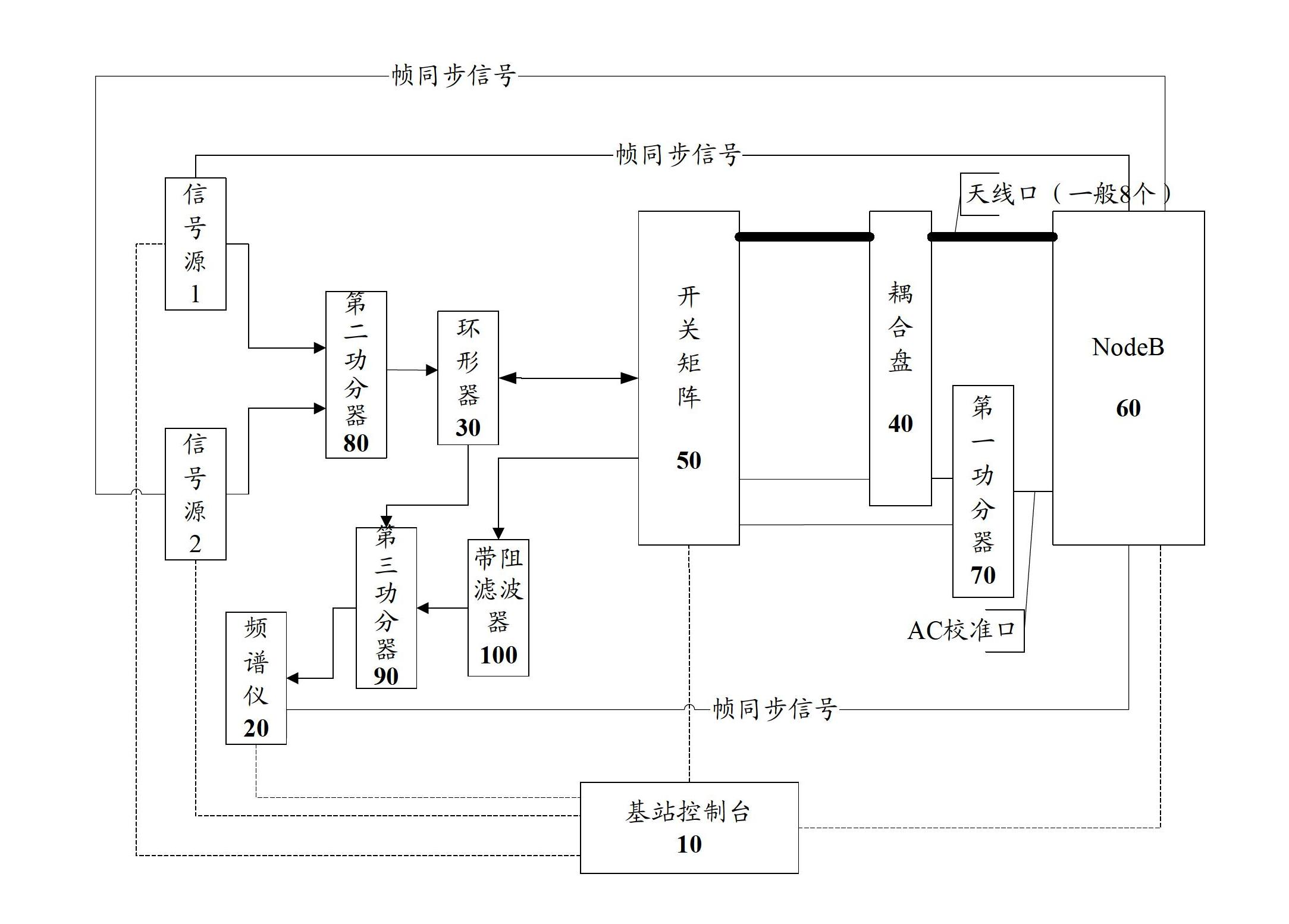
[0031] refer to image 3 , shows a schematic structural diagram of a base station testing system according to Embodiment 1 of the present invention.

[0032] The base station test system of this embodiment includes: a base station console 10, a plurality of signal sources, a spectrum analyzer 20, a circulator 30, a coupling plate 40, a switch matrix 50, a base station to be tested 60, a first power divider 70, a second power divider Divider 80, third power divider 90 and band rejection filter 100.

[0033] The base station console 10 is connected to a plurality of signal sources, a spectrum analyzer 20 , a switch matrix 50 , and a base station to be tested (ie, a NodeB to be tested) 60 through network cables. Each signal source in the plurality of signal sources is connected to the second power divider 80 while being connected to the base station console 10, and then connected to the circulator 30 through the second power divider 80, and the circulator 30 is further connected...

Embodiment 2

[0049] refer to Figure 4 , shows a schematic structural diagram of a base station testing system according to Embodiment 2 of the present invention.

[0050] The base station test system of this embodiment adds a programmable power supply 200 on the basis of the test system shown in the first embodiment. In this embodiment, the program-controlled power supply 200 is an example of a 48V program-controlled power supply, but it is not limited thereto. In actual use, any other program-controlled power supply can be implemented with reference to this embodiment.

[0051] The programmable power supply 200 of this embodiment is connected between the base station console 10 and the base station to be tested 60 (the NodeB to be tested in the first embodiment is still used), and receives the control of the base station console 10 . On the one hand, during the radio frequency test of the base station, power is supplied to the base station 60 to be tested or the radio frequency remote e...


PUM


Abstract

The invention provides a base station testing system and a base station testing method. The base station testing system comprises a first power divider, a second power divider, a third power divider and a band elimination filter; the first power divider is used for dividing antenna calibration port signals sent by a base station to be tested into two paths and respectively sending the two paths of the antenna calibration port signals to a coupling disc and a switching matrix to carry out antenna calibration testing; the second power divider is used for generating one or a plurality of interference signals from a plurality of signal sources according to a control command of a base station console and simultaneously sending the interference signals to the base station to be tested by a circulator and the switching matrix so as to carry out blockage and/or intermodulation testing together with a radio frequency signal transmitted by the system; and the third power divider is used for receiving the radio frequency signal sent by the switching matrix by the band elimination filter and carrying out coexistence and co-location testing on the received radio frequency signal together with the band elimination filter. By the adoption of the base station testing system and method provided by the invention, all indexes required by the standard can be tested on one platform.

Description

technical field [0001] The present application relates to the technical field of communications, and in particular to a base station testing system and method. Background technique [0002] With the development of mobile communication technology, the communication network becomes more and more large and complex, and the operation quality of the communication network is also more and more concerned by people. The operation quality of the communication network not only affects the customer satisfaction, but also relates to the operation cost, which affects the interests of the operation and maintenance providers. [0003] One of the means to ensure the operation quality of the communication network is to conduct radio frequency tests on the base stations of the communication network, including transmitter tests and receiver tests. According to "3GPP TS 36.141 V8.0.0 (2008-09)", testing the indicators of the transmitter and receiver requires setting up environments separately....

Claims


Application Information

Patent Timeline
Patent Type & Authority Applications(China)
IPC IPC(8): H04W24/00H04W88/08
Inventor 李江涛马亮程远杰刘长太
Owner DATANG MOBILE COMM EQUIP CO LTD
Why Eureka
Try Eureka