
Wireless cholecystoscope system

A cholecystoscope, wireless technology, applied in the field of medical devices, to achieve the effect of maintaining clarity, increasing operational flexibility, and improving safety

Inactive Publication Date: 2012-10-03
GUANGZHOU BAODAN MEDICAL INSTR TECH
View PDF4 Cites 2 Cited by
  • Summary
  • Abstract
  • Description
  • Claims
  • Application Information

AI Technical Summary

Problems solved by technology

However, in the prior art, the wireless technology has not been applied to the cholecystoscope. Therefore, it is imminent to develop a wireless cholecystoscope system integrating wireless technology.

Method used


Image

  • Wireless cholecystoscope system
  • Wireless cholecystoscope system
  • Wireless cholecystoscope system

Examples


Embodiment 1

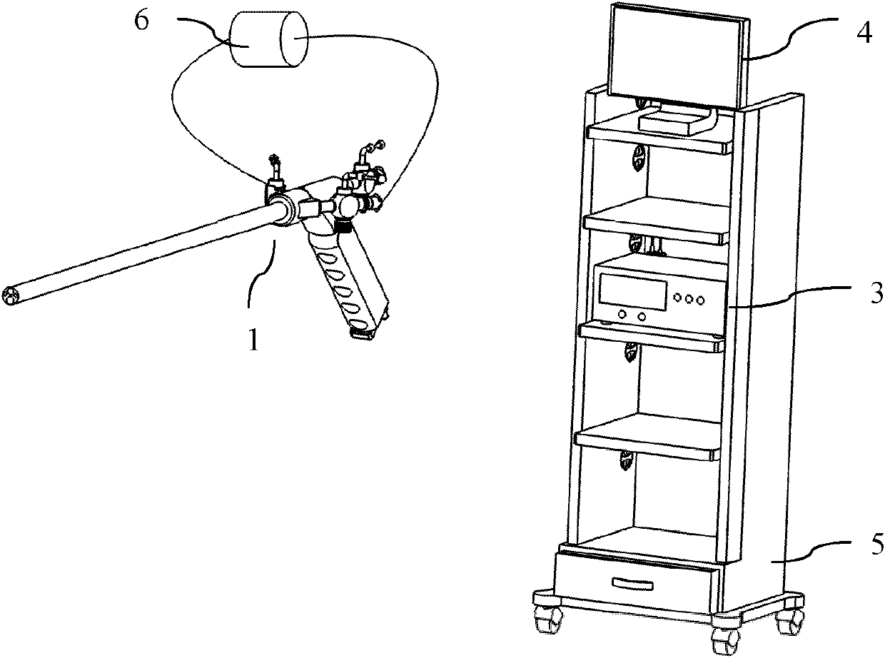
[0020] Such as figure 1 , Figure 5 As shown, the wireless cholecystoscope system of the present invention includes a cholecystoscope 1 , a wireless receiving host 3 , a monitor 4 , a trolley 5 and a portable water injection device 6 .

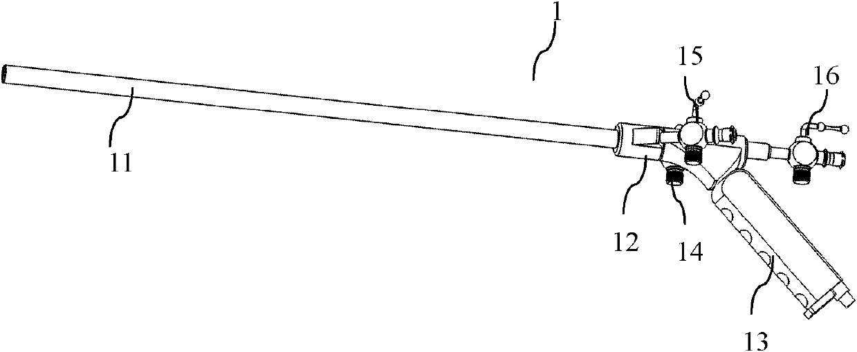
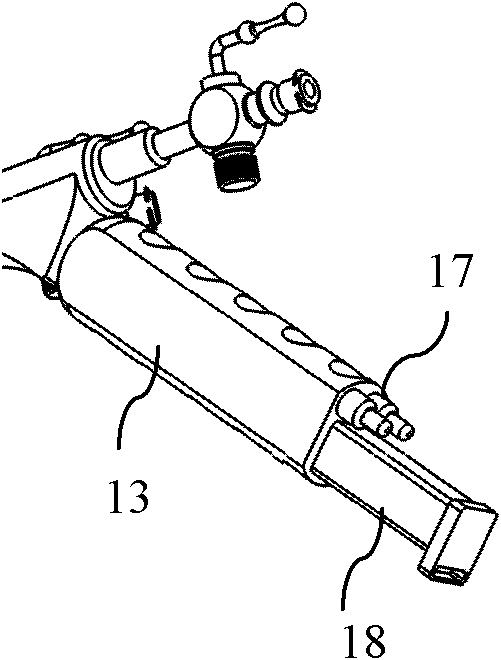
[0021] Such as figure 2 As shown, the cholecystoscope 1 includes an endoscope main body 12 and an endoscope working end 11. The endoscope main body 12 is provided with an instrument channel 14, a water inlet channel 15 and a water outlet channel 16. The endoscope working end The tip of 11 is integrated with instrument channel outlet, water inlet channel outlet, water outlet channel outlet and CCD module (not shown in the figure), and said endoscope main body 12 is also provided with operating handle 13, wireless module 17 and light source device The optical / power device 18 that integrates the module and the power supply also includes a wireless receiving host 3 used in conjunction with the wireless module 17; the wireless module 17 includes...

Embodiment 2

[0026] This embodiment is basically the same as Embodiment 1, the difference is that, as Figure 4 As shown, the structure of the endoscope main body 12 of the cholecystoscope 1 is different, the light source module 19 and the power supply 20 are designed separately, the light source module 19 is placed on the endoscope main body 12, and the wireless The module 17' and the power supply 20 are placed on the operating handle 13. The power supply 20 is a portable power supply. The function of the portable power supply 20 is to provide electric energy for the normal operation of the CCD module and the wireless module. The portable power supply 20 can be disassembled and recharged; The light source module 19 converts electrical energy into light energy to meet the needs of the wireless cholecystoscope system. The light source module can be disassembled and recharged repeatedly.


PUM

PropertyMeasurementUnit
Outer diameteraaaaaaaaaa
The inside diameter ofaaaaaaaaaa
Outer diameteraaaaaaaaaa

Abstract

The invention belongs to the field of medical instruments and particularly discloses a wireless cholecystoscope system. The wireless cholecystoscope system comprises a cholecystoscope, the cholecystoscope comprises an endoscope body and an endoscope work end, wherein the endoscope body is provided with an instrument passage, a water inlet passage, a water outlet passage, an operating handle, a wireless module,a light source module, a power source and a wireless receiving main unit. The wireless receiving main unit is used with the wireless module which comprises a processing portion and a wireless transmitting portion. The wireless receiving main unit comprises a control panel, a main unit circuit and a receiving module used for receiving signals sent from the wireless transmitting module, and a monitor is connected to the main unit circuit. After being processed by the wireless module, CCD images acquired are transmitted to the wireless receiving main unit in a wireless signal form, received and processed by the wireless receiving main unit, and then transmitted to the monitor to be output. The conventional complicated circuits can be omitted by the wireless cholecystoscope system, so that images can be transmitted by the simplest, directest and most efficient wireless technique, doctors can be released, flexibility in operation is improved and safety of operation is also improved.

Description

technical field [0001] The invention belongs to the field of medical instruments, and in particular relates to a wireless cholecystoscope system. Background technique [0002] At present, wireless technology is very mature, and its advantages are obvious. Through wireless, it can achieve long-distance and efficient information transmission. Through air as a medium, it can reduce the complexity of conventional transmission lines and achieve the purpose of simplifying the structure. At present, there are FM wireless technology, infrared wireless technology and Bluetooth wireless technology. [0003] Combining wireless technology with clinical endoscopy technology can not only simplify the surgical environment, but also make the endoscope easy to disinfect and increase the efficiency of equipment use; due to the simplification of the disinfection process, the operating room produces less pollutants, from the perspective of environmental protection It is said that to a certain ...

Claims


Application Information

Patent Timeline
IPC IPC(8): A61B1/313A61B5/07
Inventor 乔铁
Owner GUANGZHOU BAODAN MEDICAL INSTR TECH
Learn More