Intelligent diamond cutter with real-time sensing and monitoring system and cutter body matched with intelligent diamond cutter
A diamond tool and monitoring system technology, applied in lathe tools, manufacturing tools, tool holder accessories, etc., can solve the problems of inability to meet the requirements of measurement accuracy and sensitivity, large equipment volume, and insufficient practicability, etc., to achieve Comprehensive and powerful functions, high measurement sensitivity, simple and compact structure
- Summary
- Abstract
- Description
- Claims
- Application Information
AI Technical Summary
Problems solved by technology
Method used
Image
Examples
specific Embodiment approach 1
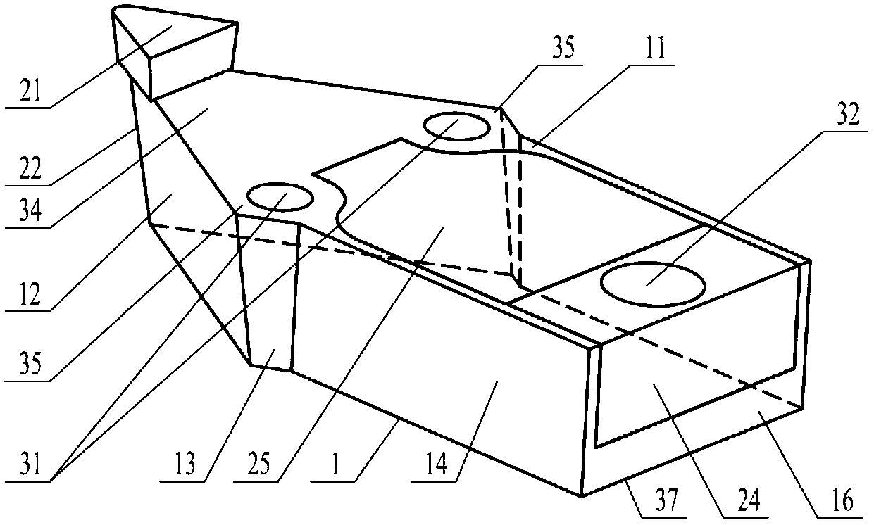
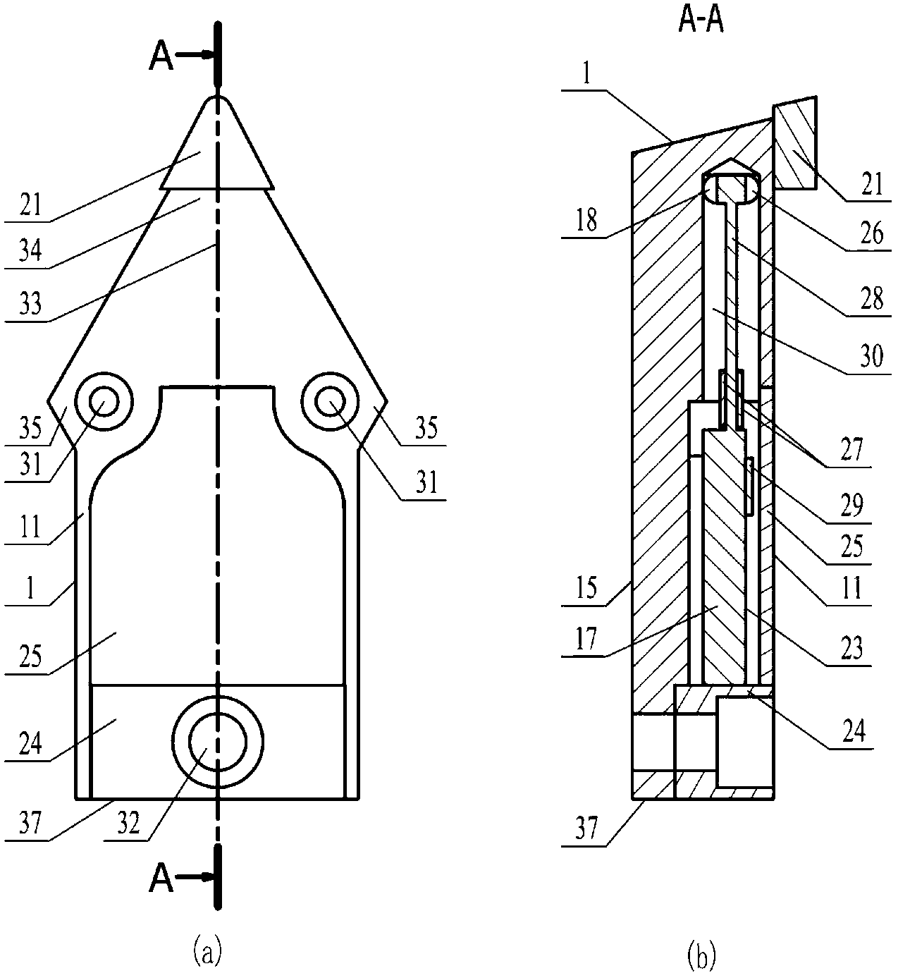
[0018] Specific implementation one: as figure 1 , figure 2 (a), figure 2 (b) and Image 6 As shown, there is an intelligent diamond tool with a real-time perception monitoring system, the intelligent diamond tool 1 includes a diamond blade 21 and a tool base 22, and the diamond blade 21 is consolidated on the front end of the upper surface 11 of the tool base 22 for cutting workpieces, and the diamond blade The front end of 21 is placed outside the tool base 22, and the intelligent diamond tool 1 also includes a microelectromechanical sensing system 23, a rear sealing pressure pad 24 and an upper sealing cover 25; the microelectromechanical sensing system 23 includes a temperature sensor 26 , chip 17, perception measurement long arm cantilever beam 28, acceleration sensor 29, information processing and wireless transmission module and two strain sensors 27,
[0019] The front end of the tool base 22 is provided with a sharp corner area 34, the rear end of the tool base 22...
specific Embodiment approach 2
[0022] Specific implementation two: as figure 1 , figure 2 (a) and figure 2 (b) and Image 6 As shown in the specific embodiment one, the external structure of the tool base 22 is composed of an upper surface 11, a lower surface 15, a rear end surface 16, two front sides 12, two tool positioning sides 13 and two rear sides 14. The upper surface 11 and the lower surface 15 are arranged up and down horizontally facing each other, the two front sides 12 are symmetrically arranged between the upper surface 11 and the lower surface 15 with respect to the longitudinal midsection 33 of the tool base 22, and the front ends of the two front sides 12 are arranged to intersect, The upper and lower ends of the two front sides 12 are respectively intersected with the upper surface 11 and the lower surface 15 and are arranged at a certain inclination angle with it. The blade 21 is arranged at the front end in the sharp corner area 34 of the knife, the two rear sides 14 are arranged in ...
specific Embodiment approach 3
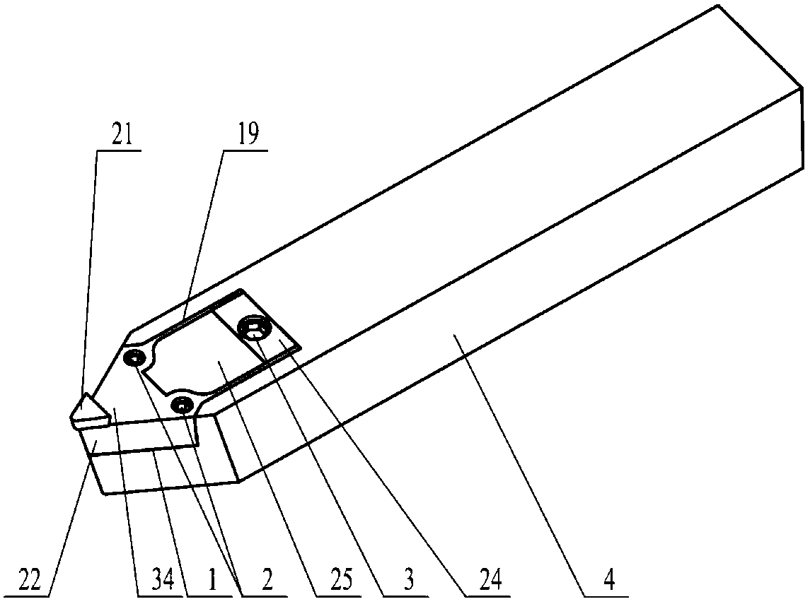
[0023] Specific implementation three: as figure 1 , image 3 , Figure 4 and Figure 5 As shown, the cutter body is paired with the intelligent diamond cutter of the second embodiment; the cutter body includes an intelligent diamond cutter 1 and a cutter handle 4, and the front end of the upper surface of the cutter handle 4 is machined with a The matching installation grooves 19, the intelligent diamond tool 1 is placed in the installation groove 19 of the tool holder 4, the lower surface 15 of the tool base 22 in the intelligent diamond tool 1 and the two tool positioning side surfaces 13 are used for the installation groove 19. Corresponding positioning surfaces are paired and positioned, the two first set screws 2 are fastened to the tool shank 4 through the two first screw locking holes 31 , and the second set screws 3 are fastened through the second screw locking holes 32 . fixed on the handle 4.
PUM
 Abstract
Description
Claims
Application Information
 - R&D
- Intellectual Property
- Life Sciences
- Materials
- Tech Scout
- Unparalleled Data Quality
- Higher Quality Content
- 60% Fewer Hallucinations
Browse by: Latest US Patents, China's latest patents, Technical Efficacy Thesaurus, Application Domain, Technology Topic, Popular Technical Reports.
© 2025 PatSnap. All rights reserved.Legal|Privacy policy|Modern Slavery Act Transparency Statement|Sitemap|About US| Contact US: help@patsnap.com


