
Improved structure of laser machining device

A technology of processing equipment and improved structure, applied in metal processing equipment, manufacturing tools, welding equipment, etc., can solve problems such as limited processing freedom, improve production efficiency and product yield, increase production costs, and be less prone to damage Effect

Inactive Publication Date: 2012-10-03
镒生电线塑料(昆山)有限公司
View PDF10 Cites 0 Cited by
  • Summary
  • Abstract
  • Description
  • Claims
  • Application Information

AI Technical Summary

Problems solved by technology

[0002] In existing laser processing machines, the laser light source is based on the X-Y axis as the common specification. However, when processing some elastic materials, the degree of freedom of processing is limited because there is only two-dimensional plane movement.

Method used


Image

  • Improved structure of laser machining device

Examples


Embodiment Construction

[0009] Embodiments of the improved structure of the laser processing device of the present invention will be described in detail below with reference to the accompanying drawings.

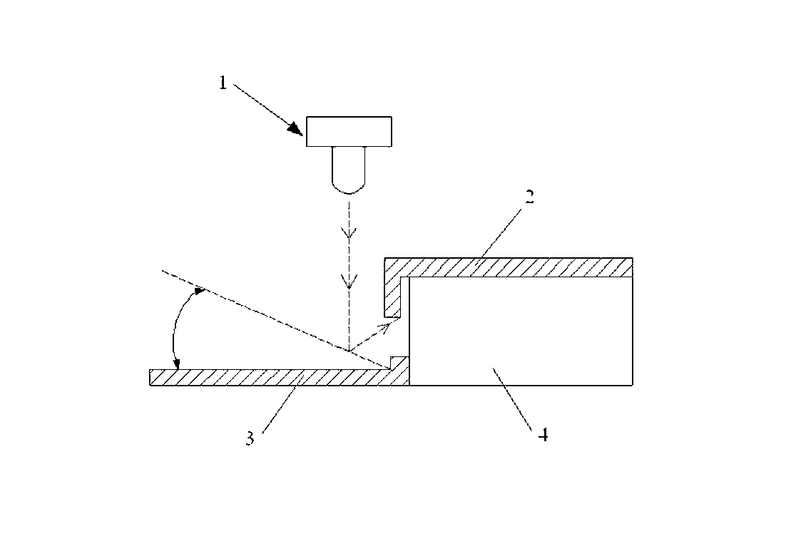
[0010] An improved structure of a laser processing device of the present invention includes a laser light source 1, a laser work table and a workpiece 2, a movable reflector 3 is arranged on the laser work table, the reflector and the laser The light source is arranged oppositely, and the workpiece is located between the reflector and the laser light source.

[0011] In this embodiment, a pedestal 4 is also provided on the laser working table, and the workpiece is placed on the pedestal.

[0012] In this embodiment, the reflector has an L-shaped plate structure, and the corner of the reflector divides it into two long strips, one of which is hinged on the base, and the other long The strip segment can be displaced relative to the laser table.


PUM


Abstract

The invention discloses an improved structure of a laser machining device. The improved structure of the laser machining device comprises a laser light source, a laser working tabletop and a workpiece. A movable reflecting part is arranged on the laser working tabletop, and is opposite to the laser light source. The workpiece is positioned between the reflecting part and the laser light source. The laser light source can be precisely condensed on the machined part of the workpiece, so that the production efficiency and the yield of a product are effectively improved.

Description

technical field [0001] The invention relates to the field of a laser processing device, in particular to an improved structure of a laser processing device. Background technique [0002] In existing laser processing machines, the laser light source is based on the X-Y axis as the common specification. However, when processing some elastic materials, the degree of freedom of processing is limited because there is only two-dimensional plane movement. Contents of the invention [0003] In order to overcome the above-mentioned defects, the present invention provides an improved structure of a laser processing device. The structure is simple and can precisely focus the laser light source on the processing part of the workpiece, which greatly improves the yield rate and work efficiency of the workpiece. [0004] The technical solution adopted by the present invention in order to solve the technical problem is: an improved structure of a laser processing device, including a laser...

Claims


Application Information

Patent Timeline
IPC IPC(8): B23K26/04B23K26/064
Inventor 严福笙黄君逸
Owner 镒生电线塑料(昆山)有限公司
Features
  • Generate Ideas
  • Intellectual Property
  • Life Sciences
  • Materials
  • Tech Scout
  • Unparalleled Data Quality
  • Higher Quality Content
  • 60% Fewer Hallucinations
Learn More