Assembling and positioning jig in blood sampling needle automatic assembling equipment

A technology for positioning jigs and assembling equipment, applied in manufacturing tools, workpiece clamping devices, etc., can solve the problems of the spring 4 failing to correctly launch the needle core 3, the card 10 being stuck, blood sampling failure, etc., and achieving simple structure and assembly position. Correct, low-cost effects

Active Publication Date: 2012-10-03
STERILANCE MEDICAL SUZHOU
View PDF8 Cites 4 Cited by
  • Summary
  • Abstract
  • Description
  • Claims
  • Application Information

AI Technical Summary

Problems solved by technology

However, when the needle core 3 is pulled, the needle core 3 will easily drive the spring 4 to move, causing the tail of the spring 4 to tilt up.
The above-mentioned problems will lead to the result that the card 10 cannot be stuck on the spr

Method used


Image

  • Assembling and positioning jig in blood sampling needle automatic assembling equipment
  • Assembling and positioning jig in blood sampling needle automatic assembling equipment
  • Assembling and positioning jig in blood sampling needle automatic assembling equipment

Examples


Embodiment

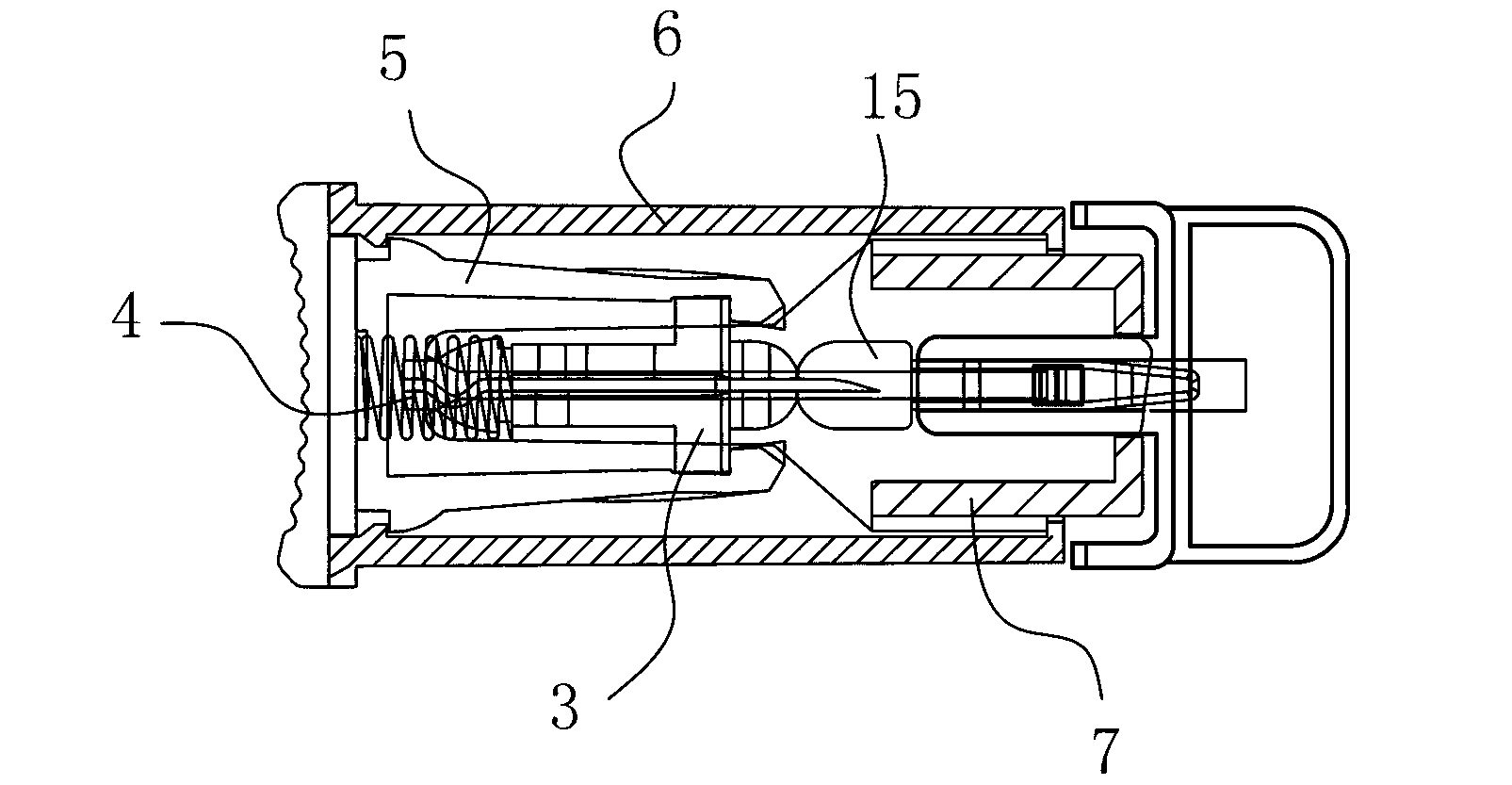
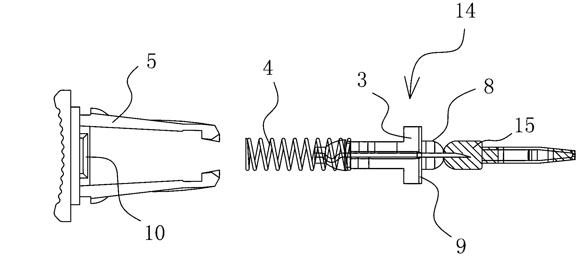
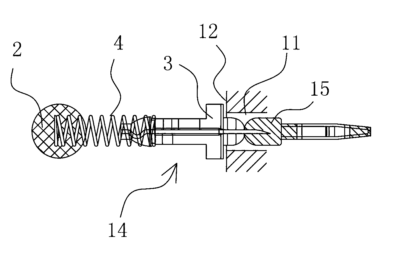
[0021] Example: see attached Figure 3-6 As shown, an assembly and positioning fixture in the automatic assembly equipment of blood collection needles is aimed at the core spring assembly 14 in the blood collection needle. The station 13 of the core spring assembly 14 can balance the force. On the station 13, a U-shaped positioning groove 11 is arranged corresponding to the journal 8 of the needle core 3 in the needle core spring assembly 14, and the U-shaped positioning groove 11 corresponds to the needle. One end of the first end face 9 of the core 3 is provided with a positioning end face 12; on the station 13, a magnetic positioning block 2 is set corresponding to the tail of the spring 4 in the needle core spring assembly 14, so as to form a positioning structure for the needle core spring assembly 14.

[0022] In other examples, the number of stations 13 provided on the base 1 may be one, three, four or other according to the specific usage, as long as it is convenient f...


PUM


Abstract

The invention relates to an assembling and positioning jig in blood sampling needle automatic assembling equipment, which is characterized in that aiming at a needle core spring assembly (14) in a blood sampling needle, the assembling and positioning jig is provided with a base (1); at least one station (13) for positioning the needle core spring assembly (14) is arranged on the base (1); a U-shaped positioning groove (11) is arranged at the position on the station (13), which corresponds to a shaft neck (8) of a needle core (3) in the needle core spring assembly (14); a positioning end face (12) is arranged at the end of the U-shaped positioning groove (11), which corresponds to a first end face (9) of the needle core (3); a magnetic positioning block (2) is arranged at the position on the station (13), which corresponds to the tail part of a spring (4) in the needle core spring assembly (14), so as to form a positioning structure of the needle core spring assembly (14). The assembling and positioning jig in the scheme can be used for positioning the needle core spring assembly when the blood sampling needle is automatically assembled, the yield of a product is greatly improved and the blood is ensured to be successfully sampled by the blood sampling needle.

Description

technical field [0001] The invention relates to automatic assembly equipment for blood collection needles, in particular to a positioning jig for assembling a three-piece set of a needle core, a spring and a tail cap in the automatic assembly equipment for blood collection needles. Background technique [0002] Lancets are used to collect blood samples during medical tests. There are many types of blood collection needles, with Figure 1-2 Shown is a single-use safety lancet. This blood collection needle is made up of needle core 3, spring 4, pusher 7, shell 6 and tail cap 5, wherein shell 6 and tail cap 5 form an ejection chamber, needle core 3 is located in the ejection chamber, and needle core 3 is provided with There is a needle body, and the front end of the needle core 3 is detachably connected with one end of a protective rod 15 by a neck that can be twisted off. The needle core 3 has a journal 8 and a first end face 9, and the other end of the protective rod 15 is ...

Claims


Application Information

Patent Timeline
IPC IPC(8): B25B11/02
Inventor 施国平
Owner STERILANCE MEDICAL SUZHOU
Why Eureka
Try Eureka