Coarse yarn circulating device in spinning frame

A circulation device and spinning frame technology, applied in textiles and papermaking, etc., can solve the problems of low work efficiency of roving workers, high labor intensity of roving workers, affecting the work of roving workers, etc., to achieve convenient transportation of roving, compact structure and simple design Effect

Inactive Publication Date: 2012-10-03
山西经纬合力机械制造有限公司四厂
View PDF9 Cites 7 Cited by
  • Summary
  • Abstract
  • Description
  • Claims
  • Application Information

AI Technical Summary

Problems solved by technology

The linear travel car is occupied by the collective doffing device attached to the spinning frame and the blowing and suction cleaner of the auxiliary machine, which affects the work of the car operator, resulting in low work efficiency of the car operator and high labor intensity of the roving worker
The use of the circulating traveling carriage effectively increases the space of the channel, allowing the roving workers to easily replace the rovings. However, due to the complex structure and high price of the roving circulating devices produced by various factories, it is difficult for textile mills to accept them, and due to the current labor cost increase, most textile mills have been looking forward to a labor-saving, cost-effective product to replace the current recycling device

Method used


Image

  • Coarse yarn circulating device in spinning frame
  • Coarse yarn circulating device in spinning frame
  • Coarse yarn circulating device in spinning frame

Examples


Embodiment Construction

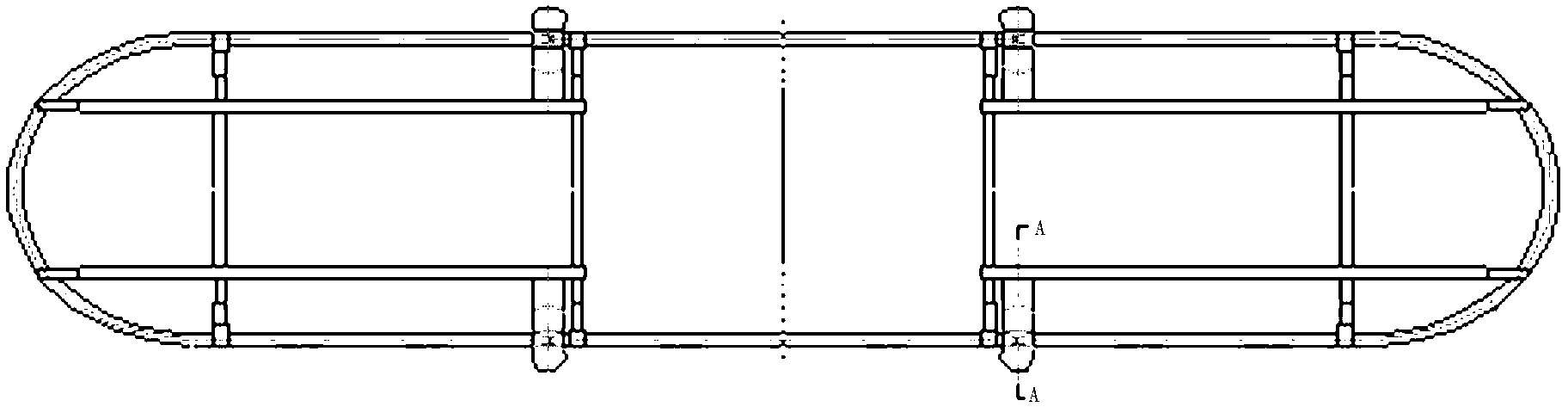
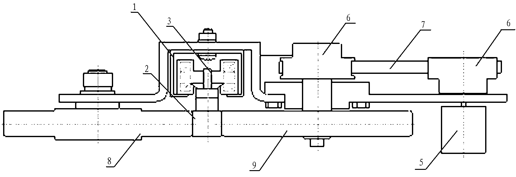
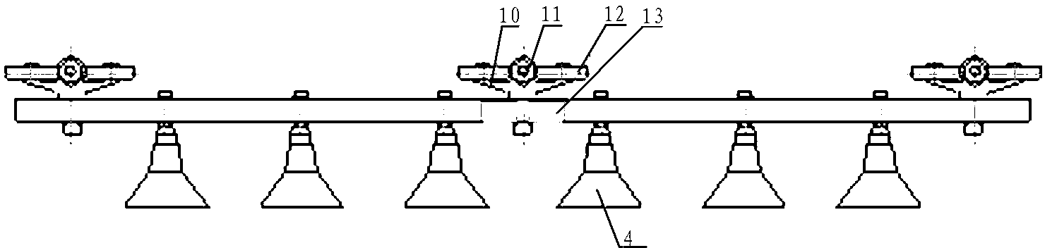
[0019] The roving circulation device in the spinning frame, which includes track 1, conveying rod 2, conveying rod guide device 3, hanging spindle 4, motor 5, gear 6, synchronous belt 7, first friction wheel 8 and second friction wheel 9, motor 5 is set under the track 1, the gear 6 is set on the output shaft of the motor 5, the first friction wheel 8 and the second friction wheel 9 are set on the track 1, the first friction wheel 8 is connected with the gear 6 through the synchronous belt 7, The conveying rod 2 is set in the groove of the track 1 through the conveying guide device 3, the hanging spindle 4 is arranged under the conveying rod 2, the two ends of the conveying rod 2 are respectively provided with hinges 13, and the adjacent hinges 13 pass through the conveying rod guiding device 3 on the shaft connection, the delivery rod 2 is located between the first friction wheel 8 and the second friction wheel 9, the first friction wheel 8, the second friction wheel 9 and th...


PUM

PropertyMeasurementUnit
diameteraaaaaaaaaa

Abstract

The invention relates to a coarse yarn circulating device in a spinning frame. A motor (5) is arranged below a track (1), gears (6) are arranged on an output shaft of the motor (5), first friction wheels (8) and second friction wheels (9) are arranged on the track (1), the first friction wheels (8) are connected with the gears (6) through synchronous belts (7), a conveying rod (2) is arranged in a groove of the track (1) through a conveying guide device (3), suspended spindles (4) are arranged below the conveying rod (2), a hinging piece (13) is arranged at each of two ends of the conveying rod (2), the adjacent hinging pieces (13) are connected through a shaft on the conveying guide device (3), the conveying rod (2) is positioned between the first friction wheels (8) and the second friction wheels (9), and the first friction wheels (8) and the second friction wheels (9) are connected with the conveying rod (2) in a rolling mode. Through the device, automatic circulating motion of coarse yarns is realized, the coarse yarns can be conveniently conveyed by roving workers, the labor intensity of the roving workers is reduced, and the working efficiency is improved.

Description

[0001] technical field [0002] The invention belongs to a part of a textile machine, in particular to a roving circulation device in a spinning frame. Background technique [0003] At present, there are two ways for the spinning frame to transport spare rovings, one is the form of linear travel, and the other is the form of circulation. The linear doffing device and the auxiliary machine blowing and suction cleaners attached to the spinning frame occupy the channel, which affects the work of the car operator, resulting in low work efficiency of the car operator and high labor intensity of the roving worker. The use of the circulating traveling carriage effectively increases the space of the channel, allowing the roving workers to easily replace the rovings. However, due to the complex structure and high price of the roving circulating devices produced by various factories, it is difficult for textile mills to accept them, and due to the current labor cost Most textile mill...

Claims


Application Information

Patent Timeline
Patent Type & Authority Applications(China)
IPC IPC(8): D01H9/18
Inventor 王亚平徐富荣赵振毅丁亚平王丽朱建中
Owner 山西经纬合力机械制造有限公司四厂
Why Eureka
Try Eureka