Bearing lubricating structure of reduction box

A bearing lubrication and reduction box technology, applied in gear lubrication/cooling, elevators in buildings, transportation and packaging, etc., can solve problems such as high cost, noise, and reduced bearing life, reduce maintenance workload, structural design Simple, vibration-damping effect

Active Publication Date: 2012-10-03
SUZHOU TORIN DRIVE EQUIP
View PDF6 Cites 9 Cited by
  • Summary
  • Abstract
  • Description
  • Claims
  • Application Information

AI Technical Summary

Problems solved by technology

In this structure, the bearing 6 is filled with lubricating grease, which is difficult to separate when water, dust, and wear debris are mixed in; when the worm shaft 1 rotates at high speed in a high-temperature environment, the stability of the lubricating grease becomes poor, and the frictional moment is relatively large. Wear and tear power consumption increases, resulting in vibration, noise, and greatly reduced bearing life. Therefore, frequent replacement of grease is required under this working condition. However, in order to replace grease, it is necessary to set up pipelines for supplying and removing grease and to collect and use them. The old grease collector is expensive, and the structural design and replacement and maintenance process are relatively cumbersome
Therefore, under high-temperature and high-speed working conditions, the structure needs to be lubricated by oil. Through the circulation of lubricating oil, a large amount of heat around the bearing and impurities are washed away, but the lubricating oil is easy to flow, so it is necessary to design a bearing with good protection. Bearing lubricating structure with oil function, which circulates lubricating oil to bearing components

Method used


Image

  • Bearing lubricating structure of reduction box
  • Bearing lubricating structure of reduction box
  • Bearing lubricating structure of reduction box

Examples


Embodiment 1

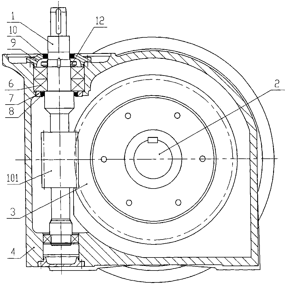
[0025] see figure 2 , in an embodiment of the present invention, the described reduction box is the worm gear box of the elevator traction machine, the described driving shaft is the worm shaft, and the worm shaft is installed vertically, specifically: the described reduction box includes a worm screw Shaft 1, main shaft 2, worm wheel 3, box body 4, both ends of the worm shaft 1 are rotatably placed on the box body 4 through rolling bearings, and one end of the worm shaft 1 extends to the outside of the box body 4 and the motor (not shown in the figure) connected. The main shaft 2 is a driven shaft, which is pivoted on the box body 4, and a worm wheel 3 is sleeved in the middle of the main shaft 2. There is a bushing 5 at the step above the threaded section 101 of the worm shaft 1, and the inner side of the lower end face of the bearing 6 installed above the threaded section 101 of the worm shaft 1 is pressed against the bushing 5, and the outer side of the lower end face ...

Embodiment 2

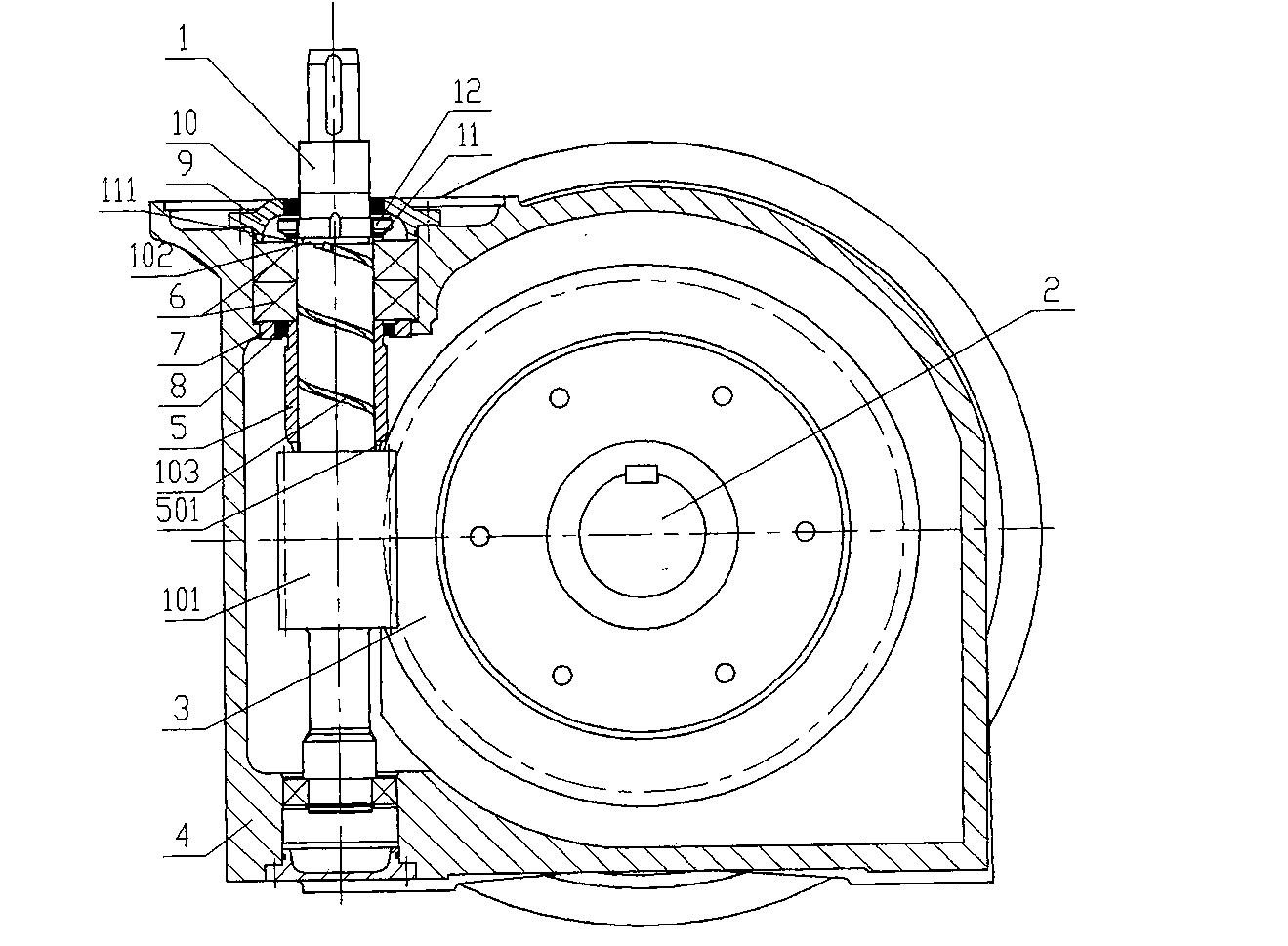
[0027] see image 3 , in another embodiment of the present invention, the described reduction box is the worm gear box of the elevator traction machine, the described driving shaft is the worm shaft, the worm shaft is installed vertically, and the reduction box includes the worm shaft 1, the main shaft 2. Worm wheel 3, box 4, both ends of the worm shaft 1 are rotatably placed on the box 4 through rolling bearings, and one end of the worm shaft 1 extends out of the box 4 and is connected to the motor (not shown in the figure). The main shaft 2 is a driven shaft, which is pivoted on the box body 4, and a worm wheel 3 is sleeved in the middle of the main shaft 2. There is a bushing 5 at the step above the threaded section 101 of the worm shaft 1. The inner side of the lower end face of the bearing 6 installed on the upper part of the worm shaft 1 is pressed against the bushing 5, and the outer side of the lower end face of the bearing 6 is pressed against the oil seal seat. 7,...

Embodiment 3

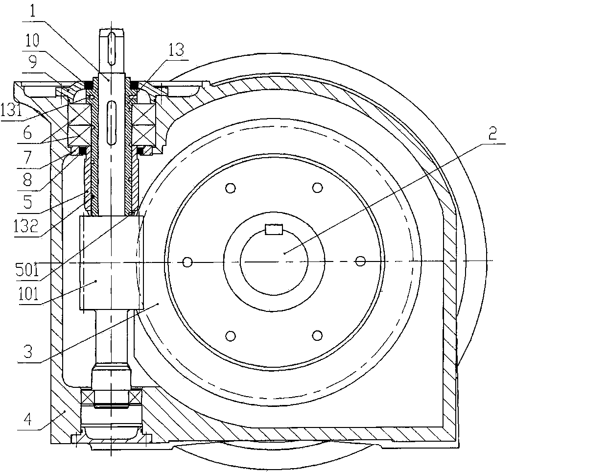
[0029] see Figure 4 , in another embodiment of the present invention, the described reduction box is the worm gear box of the elevator traction machine, the described driving shaft is the worm shaft, the worm shaft is installed vertically, and the reduction box includes the worm shaft 1, the main shaft 2. Worm wheel 3, box 4, both ends of the worm shaft 1 are rotated on the box 4 through rolling bearings, and one end of the worm shaft 1 extends out of the box 4 and is connected to the motor (not shown in the figure). The main shaft 2 is a driven shaft, which is pivoted on the box body 4, and a worm wheel 3 is sleeved in the middle of the main shaft 2. There is a journal 104 with a smaller diameter between the worm shaft section with the bearing 6 and the threaded section 101, so a second shaft sleeve 14 is sleeved on the journal 104, and the second shaft sleeve 14 is a threaded sleeve. One end is pressed against the stepped surface of the threaded section 101, the other en...


PUM


Abstract

The invention relates to a bearing lubricating structure of a reduction box, belonging to the technical field of bearing lubrication. The reduction box comprises a driving shaft and a driven shaft, wherein the driving shaft is mounted in the reduction box through a bearing; the bearing lubricating structure comprises a rotating part and a shaft sleeve, wherein the rotating part is positioned above a thread section of the driving shaft and is fixed after being integrally produced with the driving shaft or split from the driving shaft; the bearing is arranged on the rotating part; one or multiple shaft sleeves are sheathed on a shaft section on the driving shaft and from the lower end surface of the bearing to the thread section of the driving shaft; an oil inlet is formed in the end part (close to the thread section of the driving shaft) of the shaft sleeve, an oil outlet device is arranged on the rotating part which is close to the upper end surface of the bearing, a spiral groove is formed on the rotating part and / or the shaft sleeve, and during a rotation process of the rotating part, the oil inlet can be communicated with the oil outlet device through the spiral groove; and when a pair of gears in the reduction box are meshed for transmission, lubricating oil is thrown into the oil inlet and conveyed into the bearing through the spiral groove and the oil outlet device. The bearing lubricating structure has the advantages of simple structure, low cost, good bearing lubricating effect, convenience for maintenance and long service life.

Description

technical field [0001] The invention belongs to the technical field of bearing lubrication, and in particular relates to a bearing lubrication structure of a reduction box, in particular to a lubrication structure of a bearing installed above a driving shaft in a reduction box of a vertical elevator traction machine. Background technique [0002] At present, during the operation of rolling bearings, there are different degrees of relative sliding between internal components, which leads to frictional heating and component wear. In order to reduce wear, prevent corrosion, and avoid excessive working temperature caused by frictional heating, reliable lubrication must be carried out. Bearing lubrication methods are roughly divided into two types: grease lubrication and oil lubrication. Grease-lubricated bearings have a simple structure design, grease can play a great role in sealing, low maintenance costs, and long service life. However, the properties of lubricating grease ar...

Claims


Application Information

Patent Timeline
Patent Type & Authority Applications(China)
IPC IPC(8): F16H57/04B66B11/04
Inventor 曹建文曹宇王东平陶维玉周卫李伟才程敏蕾
Owner SUZHOU TORIN DRIVE EQUIP
Why Eureka
Try Eureka