Supercharge Your Innovation With Domain-Expert AI Agents!

Horizontal type hot blast stove

A hot blast stove, horizontal technology, applied in the field of horizontal vertical fire tube hot blast stove, can solve the problems of reducing the comfort of the breeding environment, unavoidable heat dissipation wind, unfavorable for cleaning carbon deposits, etc., and achieve the effect of strengthening heat transfer and realizing Automatic furnace sealing function to improve the combustion effect

Inactive Publication Date: 2012-10-03
蒋恩良
View PDF9 Cites 4 Cited by
  • Summary
  • Abstract
  • Description
  • Claims
  • Application Information

AI Technical Summary

Problems solved by technology

The disadvantages of vertical vertical fire tube hot blast furnace are:
[0003] 1 Because the high-temperature flue gas generated when the fuel on the grate burns directly washes down the tube plate and enters the pyrotechnic tube bundle, this distance will be relatively short. When the amount of coal burned increases and the combustion intensity increases, insufficient combustion is almost inevitable. 2 The cooling air is blown in from the air-cooled interlayer of the combustion chamber, and continues to dissipate heat for the pyrotechnic tube bundle through the air-cooled interlayer upwards. The heat exchange method between the cooling air and the heat dissipation structure belongs to longitudinal flushing, which is much worse than horizontal flushing.
3. Excessive smoke temperature in the upper smoke chamber wastes heat and is not conducive to removing carbon deposits. When cleaning carbon deposits, carbon deposits fall on the fuel layer below and smoke will occur.
4. The lower tube plate and the lower tube end of the vertical fire tube hot blast stove are in a state of dual effects of thermal expansion stress and local high temperature, and the service life is limited
5 When the required heating temperature is reached, it is difficult to close the furnace easily, so that the inability to brake will cause waste of fuel and excessive temperature
6. Because the hot air blown by the hot blast stove is high in temperature and does not contain moisture, high temperature and low humidity will greatly reduce the comfort of the breeding environment

Method used


Image

  • Horizontal type hot blast stove
  • Horizontal type hot blast stove

Examples


Embodiment Construction

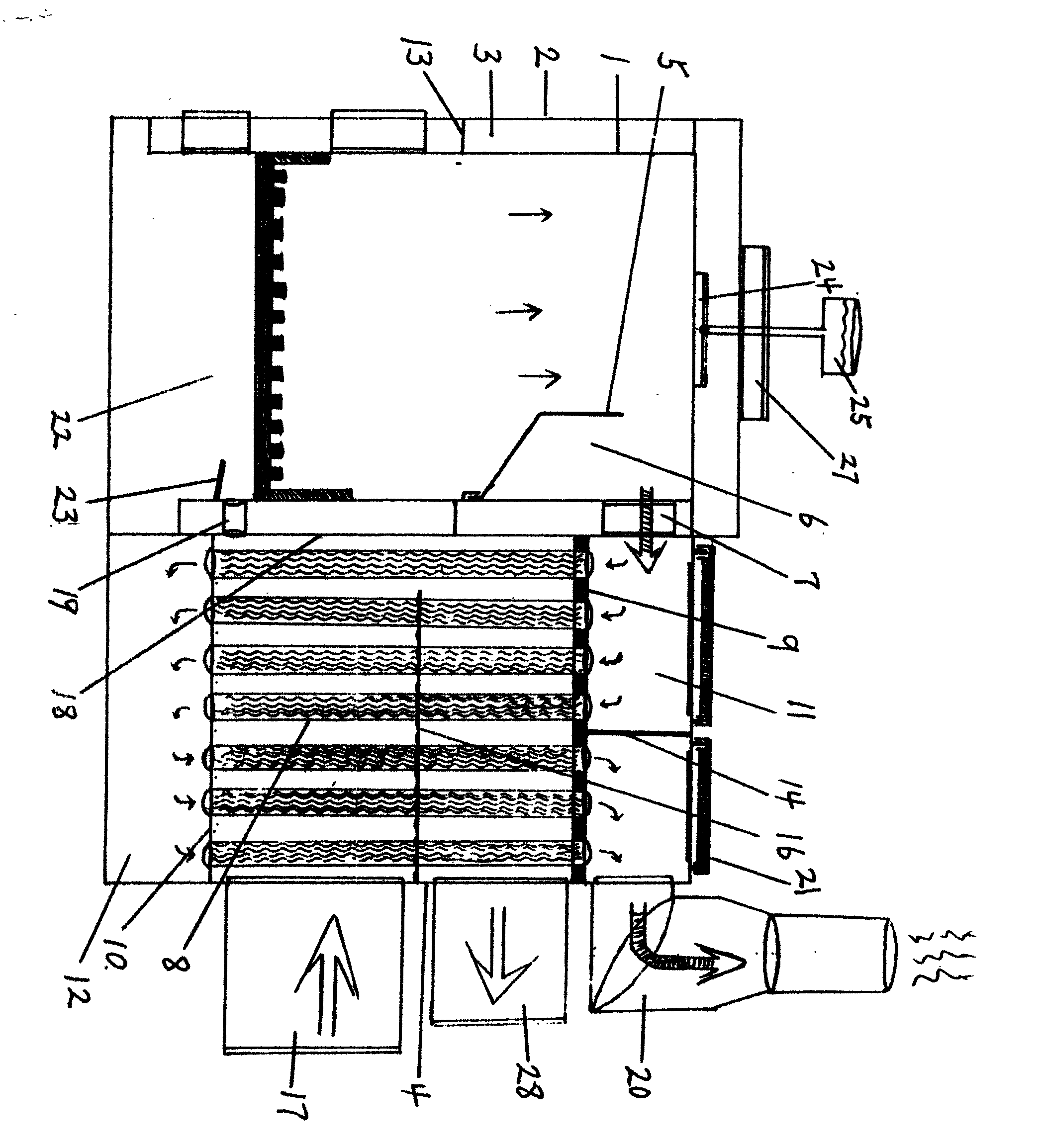
[0021] The hot blast stove is divided into two parts, a relatively independent combustion chamber and a radiator. Above the combustion chamber, there is a buffer plate 5 and a settling chamber 6 formed by the buffer plate. There is a high-temperature flue gas outlet 7 leading to the smoke chamber on the first stroke of the radiator near the radiator.

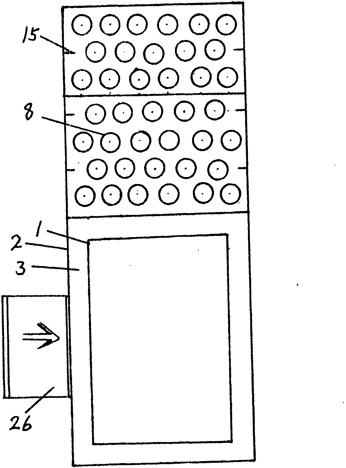
[0022] There is an air-cooled interlayer 3 between the combustion chamber liner 1 and the shell 2, and an air-cooled interlayer at the top of the combustion chamber. The radiator shell 4 and the combustion chamber shell are essentially integral structures.

[0023] The pyrotechnic tube bundle composed of pyrotechnic tubes 8 is between the upper tube plate 9 and the lower tube plate 10, the upper tube plate is the upper smoke chamber 11, and the lower tube plate is the lower smoke chamber 12.

[0024] A transverse partition 13 is arranged between the interlayer of the combustion chamber and the outer casing. The transverse partit...


PUM


Abstract

The invention relates to a horizontal type hot blast stove which belongs to the technical field of a hot blast stove. According to the horizontal type hot blast stove, the effective heat absorption area is expanded, the heat radiating blast dead angles are decreased, the heat radiating effect of a heat radiating structure is strengthened, and the heat efficiency of the hot blast stove is further improved. due to the arrangement of a buffer board arranged above a combustion chamber, a settling chamber and an upper smoke chamber arranged above an upper pipe board of a heat absorber, the running time and the running distance of high temperature smoke are relatively prolonged and increased, so as to realize sufficient burning of fuel. An intermediate pipe board arranged between the upper pipe board and a lower pipe board divides a smoke and fire tube into upper and lower parts, so that heat radiating gas of a heat radiator travels along two paths. The smoke and fire tube and the upper pipe board adopt the non-welding assembly mode so as to reduce damage on the heat adsorption structure by thermal expansion stress. A flame retardant coating arranged on the upper pipe board can effectively prevent influence of local high temperature on the upper pipe board and pipe ends. Combustion-supporting gas is part of the heat radiating gas from the heat radiator of the smoke and fire tube, and belongs to the field of hot blast combustion supporting.

Description

Technical field [0001] The invention relates to a hot blast stove, in particular to a horizontal vertical fire tube hot blast stove. Background technique [0002] Among the types of hot blast stoves used in the aquaculture industry, the more common vertical vertical fire tube hot blast stove is composed of a combustion chamber, a lower tube plate above the combustion chamber, a pyrotechnic tube bundle, an upper tube plate, an upper smoke chamber, and a chimney. The chamber and the heat absorber are connected up and down. Its working principle is: the high-temperature flue gas produced by the fuel on the grate burning in the combustion chamber scours the upper tube plate upwards and enters the pyrotechnic tube, then reaches the upper smoke chamber, and finally passes through the chimney exhaust from the smoke outlet of the upper smoke chamber. To the outside, the heat absorbed by the combustion chamber and the heat absorbed by the pyrotechnic tube bundle are exchanged under ...

Claims


Application Information

Patent Timeline
IPC IPC(8): F24H3/08F24H9/00
Inventor 蒋恩良
Owner 蒋恩良
Features
  • R&D
  • Intellectual Property
  • Life Sciences
  • Materials
  • Tech Scout
  • Unparalleled Data Quality
  • Higher Quality Content
  • 60% Fewer Hallucinations
Learn More