

Hearth refractory material structure of carbon roasting furnace
A technology of carbon roasting furnace and refractory materials, applied in the field of refractory materials, can solve the problems of low masonry efficiency, low strength of insulation bricks, broken insulation bricks, etc., achieve high masonry efficiency, simple furnace bottom structure, and increase service life Effect
Inactive Publication Date: 2012-10-03
HENAN ANRUI HIGH TEMPERATURE MATERIALS
View PDF4 Cites 1 Cited by
- Summary
- Abstract
- Description
- Claims
- Application Information
AI Technical Summary
Problems solved by technology
The bottom structure of this carbon roasting furnace has several problems: first, there are many brick shapes, the bottom structure of the furnace is too complicated, and the efficiency of masonry is low
Second, due to the low strength of the light insulation bricks at the bottom of the furnace, during the use of the carbon roasting furnace, the insulation bricks are often broken, resulting in vicious accidents such as the sinking of the flue wall
Method used
View moreImage
Smart ImageViewing Examples

Examples
Embodiment Construction
Login to View More PUM
 Abstract
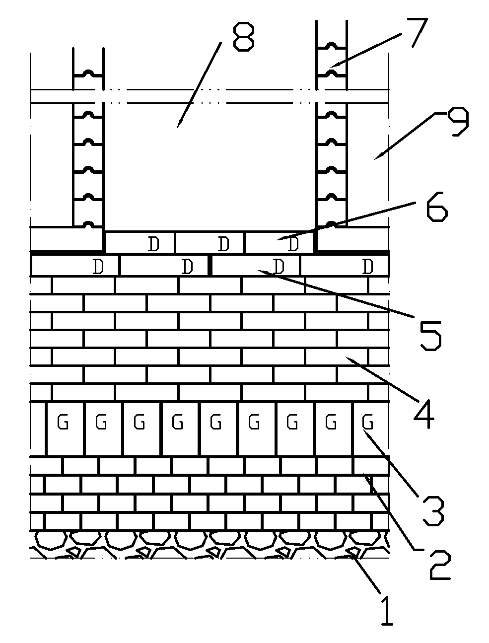
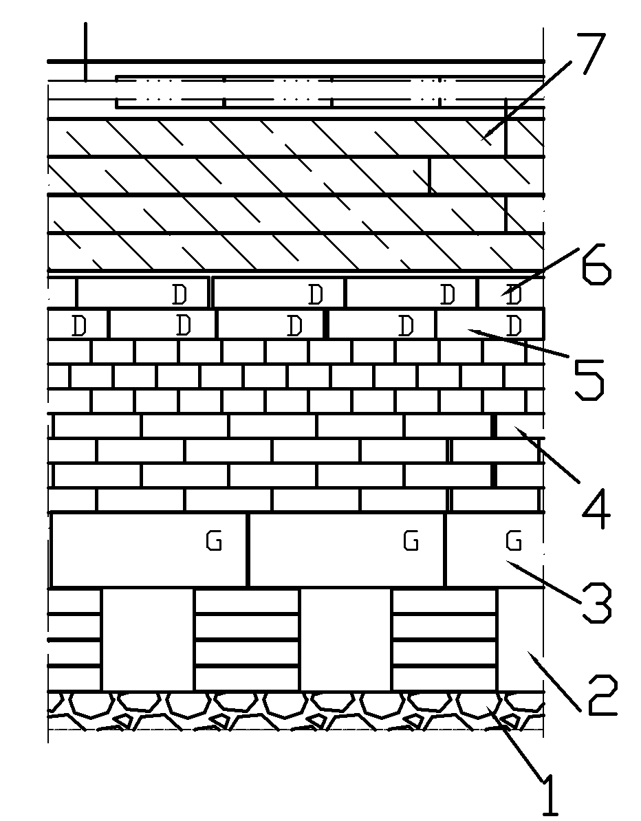
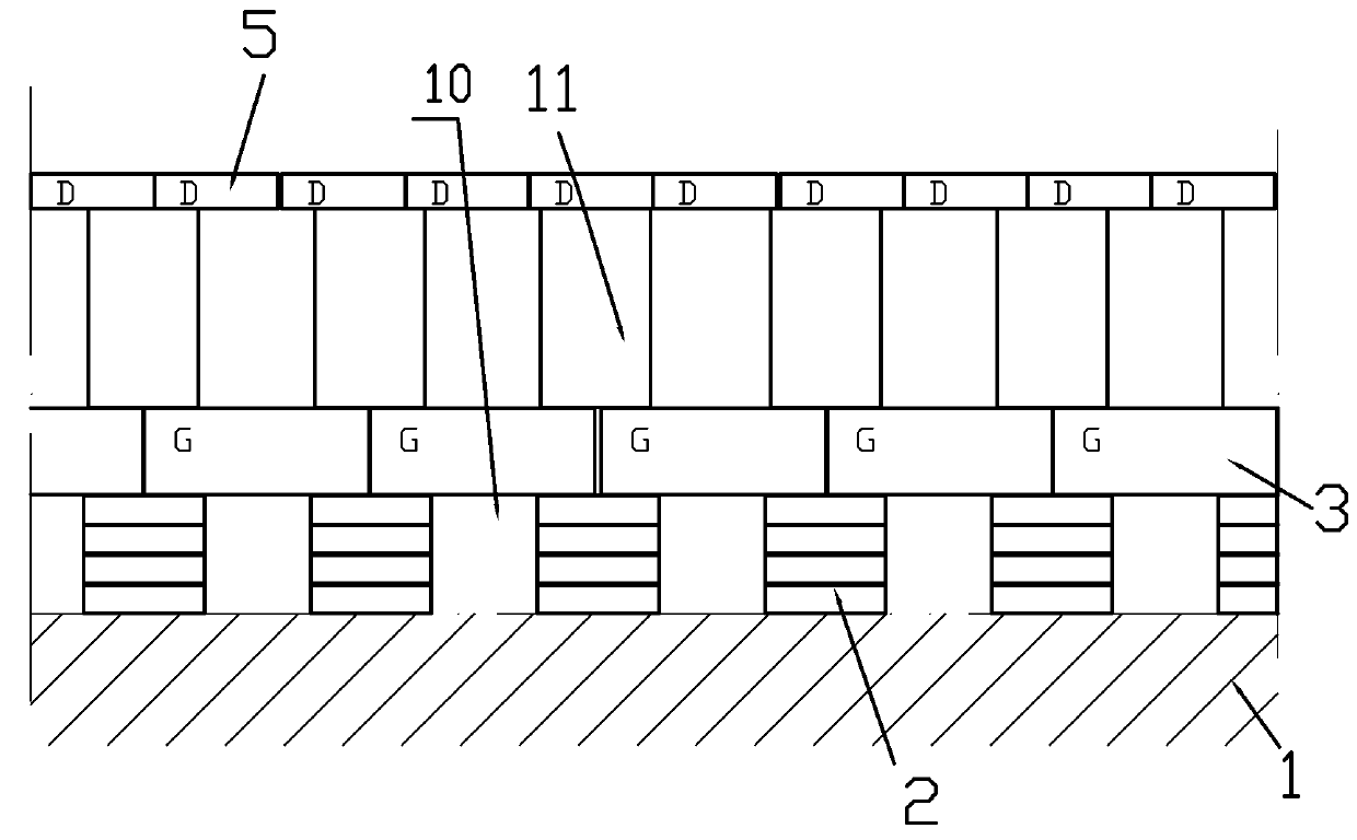
The invention discloses a hearth refractory material structure of a carbon roasting furnace. The hearth refractory material structure of the carbon roasting furnace comprises hearth heavy refractory materials or concrete, light heat-insulation bricks, hearth blocks and heavy refractory bricks at the bottom of a flame path wall, and the hearth heavy refractory materials or the concrete are connected with the heavy refractory bricks at the bottom of the flame path wall by a plurality of support columns. The hearth refractory material structure in the technical scheme has the advantages that problems that the shapes of bricks are multiple, a hearth structure is over complicated and construction efficiency is low in the prior art are solved, and problems of serious accidents such as that heat-insulation bricks are often broken and a flame path wall is subsided during usage of an existing carbon roasting furnace due to the fact that the hearth light heat-insulation bricks are low in strength and the like are also solved.
Description
technical field [0001] The invention relates to the field of refractory materials, specifically, a refractory material structure specially used in the bottom of a carbon roasting furnace and a refractory material structural component related to the structure. Background technique [0002] At present, the structure of refractory materials at the bottom of carbon roasting furnace is as follows: figure 1 and figure 2 shown. ① When building masonry, first lay several layers of refractory clay bricks on the concrete plane of the furnace bottom, generally 2-4 layers, and leave a 200-300mm wide groove, and then place the rectangular parallelepiped furnace bottom block (brick number G ) is built on top of the tank to form an overhead furnace bottom. ② Build 6-10 layers of light-weight thermal insulation refractory bricks on the top of the furnace bottom block (the total height is generally 400-600mm). The heavy refractory bricks (brick number: D) at the bottom of the flue wall...
Claims
Login to View More Application Information
Patent Timeline
 Patent Type & AuthorityApplications(China)
IPC IPC(8): F27D1/06
Inventor梁德安张启业
OwnerHENAN ANRUI HIGH TEMPERATURE MATERIALS