
Surface roughness measurement system and surface roughness measurement method

A technology of surface roughness and measurement method, which is applied in the field of surface roughness measurement system, and can solve the problems of incompleteness, low efficiency, and inability to measure probes

Inactive Publication Date: 2014-11-05
INST OF REMOTE SENSING & DIGITAL EARTH CHINESE ACADEMY OF SCI
View PDF2 Cites 7 Cited by
  • Summary
  • Abstract
  • Description
  • Claims
  • Application Information

AI Technical Summary

Problems solved by technology

The disadvantage of this method is that the contact between the probe and the ground will slightly change the original state of the ground during the measurement, the probes cannot be completely parallel, and the shape of the needle tip will affect the measurement accuracy; at the same time, the roughness plate production limited length
The disadvantage of this method is that the entire board needs to be inserted into the ground surface during measurement, which destroys the surface structure and brings certain errors to the measurement results; in addition, when the measured ground surface is too hard to be inserted into the ground surface, this method cannot measure
This method has poor flexibility in the field operation process, and needs to be adjusted and leveled during the measurement process, so the efficiency is not high; in addition, this measurement method is not suitable for the situation where the ground has large fluctuations. In the two images obtained at the same time, some surface points are in the It exists in one image, but due to the occlusion effect, the surface point does not exist in the other image, which reduces the practicality of the technical method

Method used


Image

  • Surface roughness measurement system and surface roughness measurement method
  • Surface roughness measurement system and surface roughness measurement method
  • Surface roughness measurement system and surface roughness measurement method

Examples


Embodiment Construction

[0053] The preferred embodiments of the present invention will be described below in conjunction with the accompanying drawings. It should be understood that the preferred embodiments described here are only used to illustrate and explain the present invention, and are not intended to limit the present invention.

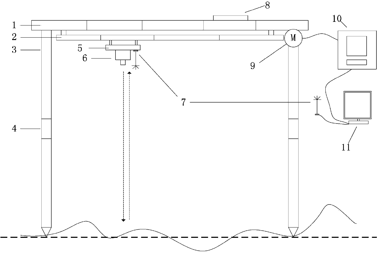
[0054] Such as figure 1 As shown, a surface roughness measuring system of the present invention includes: a support device, an electric device, a laser distance measuring device, a communication device 7, an inclination measuring device 8 and a control processing device 11, wherein:

[0055] The supporting device is the supporting body of the entire measurement system, and is used to support the electric device, the laser distance measuring device, and the inclination measuring device 8; its composition includes: a horizontal support rod 1, a horizontal guide rail 2 and a bracket 3, and the horizontal support rod 1 and the bracket 3 The top is connected, and the hor...


PUM


Abstract

The invention discloses a surface roughness measurement system and a surface roughness measurement method. The measurement system comprises a supporting device, an electric device, a laser distance measurement device, a communication device, an inclination angle measurement device and a control processing device, wherein the supporting device is used for supporting the electric device, the laser distance measurement device and the inclination angle measurement device; the electric device is used for driving the laser distance measurement device to uniformly move inthe horizontal direction of the supporting device under the control of the control processing device; the irradiation direction of the laser distance measurement device is vertically downward; the laser distance measurement device is used for measuring the distance to a ground point under the control of the control processing device and feeding the measured value back to the control processing device; the communication device is used for guaranteeing data communication between the laser distance measurement device and the control processing device; the inclination angle measurement device is used for measuring the inclination angle between the supporting device and the horizontal direction, and the control processing device is used for controlling the overall system, controlling the electric device and the laser distance measurement device to work through a transmission instruction, receiving and storing the measured data, and calculating a roughness parameter. The measurement system disclosed by the invention adopts a non-contact method to measure; the measurement direction is vertically downward, and the measurement method is suitable for various complicated and destroyed earth surfaces.

Description

technical field [0001] The invention relates to the field of three-dimensional information measurement of the earth surface, in particular to a surface roughness measurement system and a measurement method. Background technique [0002] As one of the research focuses in the field of microwave remote sensing, the surface roughness and the dielectric properties of the surface jointly affect the backscattering characteristics of radar waves. Therefore, in order to establish a correct surface microwave scattering model and promote the quantitative application of microwave remote sensing, it is necessary to correctly Describing surface roughness parameters, and measuring these surface parameters is the most critical step. The statistics describing the rough surface are mainly the root mean square height and the correlation length. These two parameters define the surface roughness from the vertical and horizontal scales respectively. [0003] For a given random rough surface, it ...

Claims


Application Information

Patent Timeline
Patent Type & Authority Patents(China)
IPC IPC(8): G01B11/30
Inventor 王国军邵芸宫华泽张风丽刘龙
Owner INST OF REMOTE SENSING & DIGITAL EARTH CHINESE ACADEMY OF SCI
Learn More