Interference optical fiber gyroscope

A fiber optic gyroscope and interferometric technology, applied in the field of gyroscopes, can solve the problems of cost increase and achieve the effects of low cost, cost reduction, high gyroscope accuracy and stability

Inactive Publication Date: 2012-10-03
PEKING UNIV
View PDF5 Cites 21 Cited by
  • Summary
  • Abstract
  • Description
  • Claims
  • Application Information

AI Technical Summary

Problems solved by technology

However, in the existing polarization-maintaining fiber optic gyroscopes and depolarization fiber optic gyroscopes, a polarizer must be installed before the fiber optic ring, or a Y-waveguide integrated optical circuit with a polarization function must be installed, which all lead to an increase in cost
For example, taking the current market price as an example, the price of a polarizer is about 3,000 yuan / piece, the price of a Y waveguide integrated optical circuit is about 6,000 yuan / piece, and the price of a polarization-maintaining optical fiber is about 20 yuan / m (while the actual gyro The length of the optical fiber ring is 100~2000 meters), and the price of the polarization maintaining coupler is about 1000~2000 yuan. , the cost is tens of thousands per piece

Method used


Image

  • Interference optical fiber gyroscope
  • Interference optical fiber gyroscope
  • Interference optical fiber gyroscope

Examples


Embodiment Construction

[0047] In the following description, for purposes of explanation, numerous specific details are set forth in order to provide a thorough understanding of one or more embodiments. It may be evident, however, that these embodiments may be practiced without these specific details. In other instances, well-known structures and devices are shown in block diagram form in order to facilitate describing one or more embodiments.

[0048] Various embodiments of the present invention will be described in detail below with reference to the accompanying drawings.

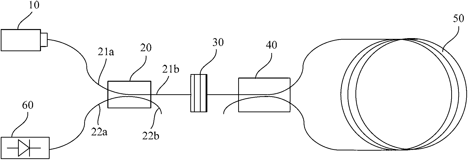
[0049] Figure 5 It is a schematic diagram of the structure of the interferometric fiber optic gyroscope described in one embodiment of the present invention. Such as Figure 5 As shown, the interferometric fiber optic gyroscope of the present invention includes: a wide-spectrum light source 10 , a light source end coupler 20 , a pre-ring depolarizer 35 , a ring end coupler 40 , a single-mode fiber ring 50 and a photodetector...


PUM


Abstract

The invention relates to an interference optical fiber gyroscope which comprises a wide-spectrum light source, a light source end coupler, a depolarizer on the front portion of a ring, a coupler at the end of the ring, a single-mode fiber ring and a photoelectric detector. The output end of the wide-spectrum light source is coupled with a first port of the light source end coupler through single-mode fiber, a third port of the light source end coupler is coupled with one end of the depolarizer on the front portion of the ring through the single-mode fiber, the other end of the depolarizer on the front portion of the ring is coupled with a first port of the coupler at the end of the ring through the single-mode fiber, a third port and a fourth port of the coupler at the end of the ring are coupled with two ports of the single-mode fiber ring through the single-mode fiber respectively, and a second port of the light source end coupler is coupled with the input end of a photoelectric detector through the single-mode fiber. The gyroscope structure omits a polarizer in a minimum reciprocity structure of a gyroscope, non-reciprocal errors are removed through decoherence and interference light intensity compensation between two polarization states, cost is greatly reduced, simultaneously noise is low, and bias stability is good.

Description

technical field [0001] The invention relates to the field of gyroscopes, in particular to an interference fiber optic gyroscope. Background technique [0002] A gyroscope is a rotational sensor used to measure the rotational angular velocity of the carrier on which it is mounted. Gyroscopes are widely used in the guidance of aircraft and weapons, precision measurement in industry and military, and other fields. The early gyroscopes were mechanical gyroscopes. Mechanical gyroscopes are directional devices manufactured using the physical principle that the rotating shaft of a high-speed rotating body has a tendency to maintain its direction. Because mechanical gyroscopes contain moving parts (such as high-speed rotors), their structures are complex, their process requirements are high, and their accuracy is restricted in many ways. [0003] In the 1960s, with the advent of lasers, the research on using lasers to manufacture optical gyroscopes developed rapidly. Optical gyro...

Claims


Application Information

Patent Timeline
Patent Type & Authority Applications(China)
IPC IPC(8): G01C19/72
Inventor 王子南王翠云杨易路萍李永啸张振荣李正斌
Owner PEKING UNIV
Why Eureka
Try Eureka