Planar laser induced fluorescence imaging measurement method for simultaneously measuring various constituent messages

A planar laser-induced, fluorescence imaging technology, applied in fluorescence/phosphorescence, material excitation analysis, etc., which can solve the problems of incomplete reaction flow field and combustion process, etc.

Inactive Publication Date: 2012-10-03
HARBIN INST OF TECH
View PDF2 Cites 22 Cited by
  • Summary
  • Abstract
  • Description
  • Claims
  • Application Information

AI Technical Summary

Problems solved by technology

[0003] In order to solve the defect that the existing method can only measure one component but cannot fully reflect the flow field and combustion process

Method used


Image

  • Planar laser induced fluorescence imaging measurement method for simultaneously measuring various constituent messages
  • Planar laser induced fluorescence imaging measurement method for simultaneously measuring various constituent messages
  • Planar laser induced fluorescence imaging measurement method for simultaneously measuring various constituent messages

Examples


specific Embodiment approach 1

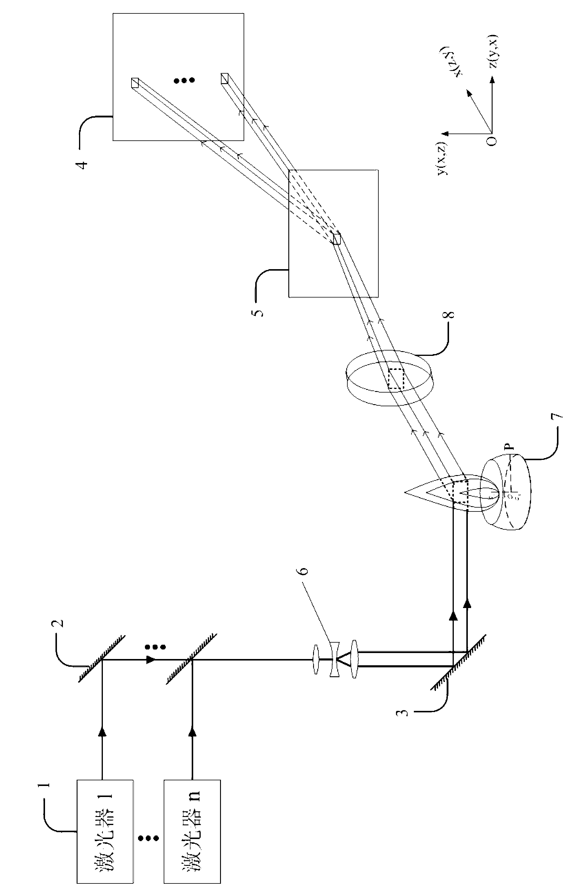
[0012] Specific implementation mode one: combine figure 1 Describe this implementation mode, the steps of this implementation mode are:

[0013] Step 1: Combining the laser beams generated by n lasers 1 into one laser beam, and then performing beam shaping through the sheet beam shaping system 6 to make it a sheet laser;

[0014] Step 2: Use the shaped sheet laser to excite the component information of the specified target area in the target flame to generate n fluorescence of different wavelengths; through the focusing lens 8 and grating 5, the n fluorescence of different wavelengths are spatially separated Separate and image on n different areas on the receiving surface of the area array ICCD4 to form n images;

[0015] Step 3: The area array ICCD4 transmits the received n images to the computer for processing and analysis, and then obtains the spatial distribution information of n components at the same time. The software used for computer processing and analysis is LBA-7...

specific Embodiment approach 2

[0017] Embodiment 2: This embodiment differs from Embodiment 1 in that the single pulse energy output by the laser 1 in step 1 is 1-30 mJ, the pulse width is 10 ns, and the repetition frequency is 10-10 kHz. Other compositions and connection methods are the same as those in Embodiment 1.

specific Embodiment approach 3

[0018] Specific implementation mode three: combination figure 1 This embodiment is described. The difference between this embodiment and the above-mentioned specific embodiments is that in step 1, the laser beams generated by n lasers 1 are combined by n mirrors 2 into one beam of laser light. Other compositions and connection modes are the same as the above-mentioned specific embodiment.


PUM

PropertyMeasurementUnit
Wavelengthaaaaaaaaaa

Abstract

The invention discloses a planar laser induced fluorescence imaging measurement method for simultaneously measuring various constituent messages, relating to the fields of energy source power and optoelectronics and solving the defects that the conventional method only can measure one constituent, but can not completely reflect flow field and combustion process. The method comprises the steps of: carrying out beam combination on the lasers generated by n laser devices to form a beam of laser, then carrying out beam shaping through a sheet beam shaping system, exciting a constituent message in an appointed target area in a target flame by a shaped sheet laser, and generating n different wavelengths of fluorescent lights; orderly separating n different wavelengths of fluorescent lights from a space through a focusing lens and a grating, respectively imaging in n different areas of an area array ICCD (intensified charge coupled device) receiving surface, transmitting n received images to a computer to process and analyze and simultaneously obtaining space distribution messages of n constituents. The method disclosed by the invention can be widely applied to diagnosis of various flow fields and combustion processes so as to provide basic data for researches of combustion science, fluid mechanics and combustion technology.

Description

technical field [0001] The invention relates to the fields of energy, power and optoelectronics, in particular to a planar laser-induced fluorescence imaging measurement method for simultaneously measuring two or more components. Background technique [0002] In recent years, with the demand for energy saving and emission reduction and the development of new aerospace propulsion technology, the research on combustion mechanism, new combustion technology, fluid mechanics and aerodynamics has become a research hotspot in the field of energy and power. The research in the above fields is inseparable from highly sensitive and high-precision diagnostic techniques. Planar Laser-Induced Fluorescence Imaging (PLIF) diagnostic technology, which began in the 20th century, is an indispensable measurement method in the above-mentioned research fields, and has been widely used in the diagnosis of various flow fields and combustion processes. However, the existing PLIF imaging diagnostic...

Claims


Application Information

Patent Timeline
IPC IPC(8): G01N21/64
Inventor 于欣彭江波杨振李晓晖樊荣伟赵永蓬陈德应李旭东董志伟贾博阳于杨
Owner HARBIN INST OF TECH
Why Eureka
Try Eureka