Mining flameproof transformer and mobile substation provided with same
An explosion-proof, transformer technology, applied in the field of transformers, can solve the problems of shortened service life, prone to condensation, corrosion of the shell, etc., to achieve the effect of eliminating horizontal and vertical seams, increasing the effective heat dissipation area, and improving the service life
- Summary
- Abstract
- Description
- Claims
- Application Information
AI Technical Summary
Problems solved by technology
Method used
Image
Examples
specific Embodiment approach 1
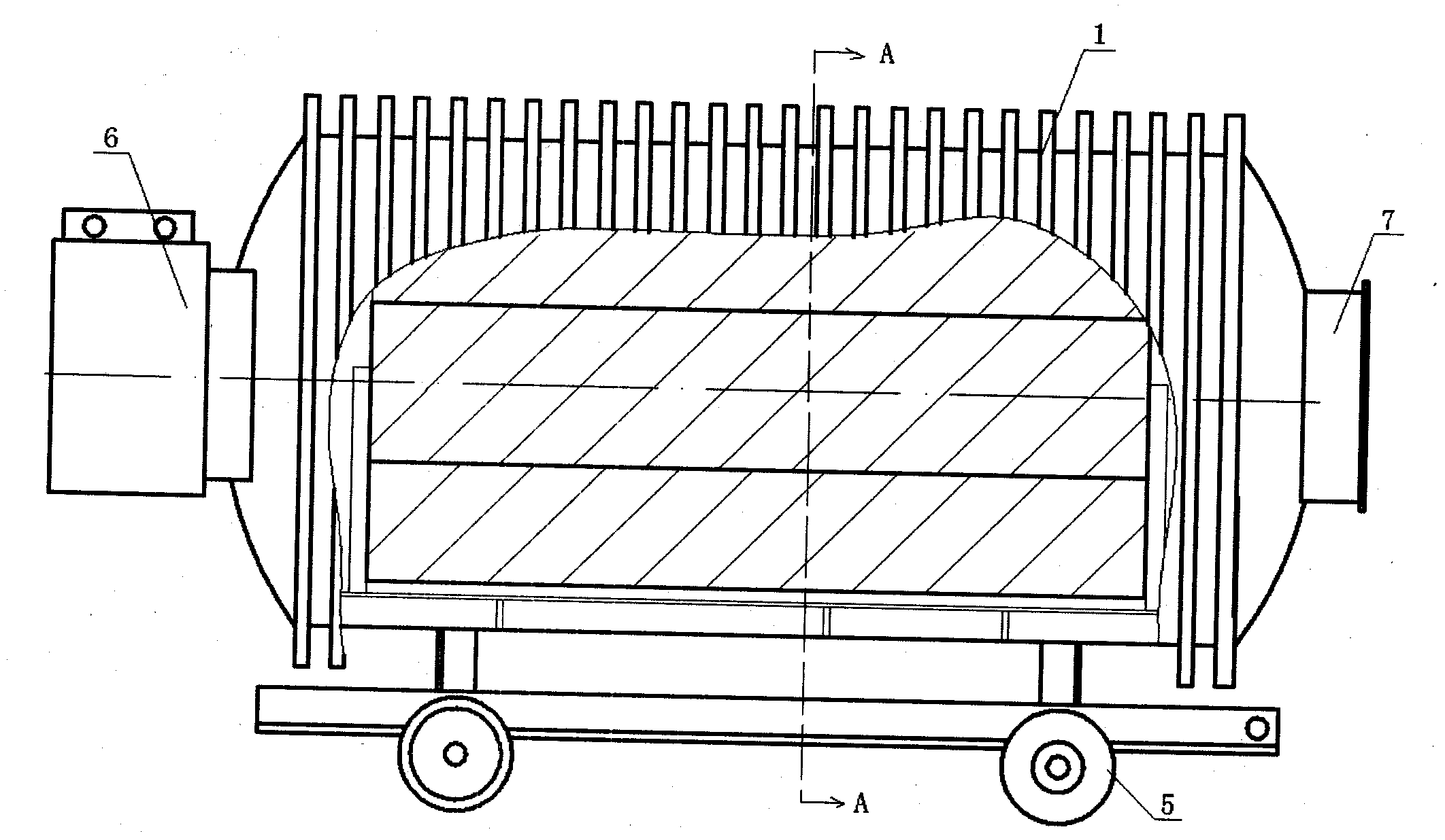
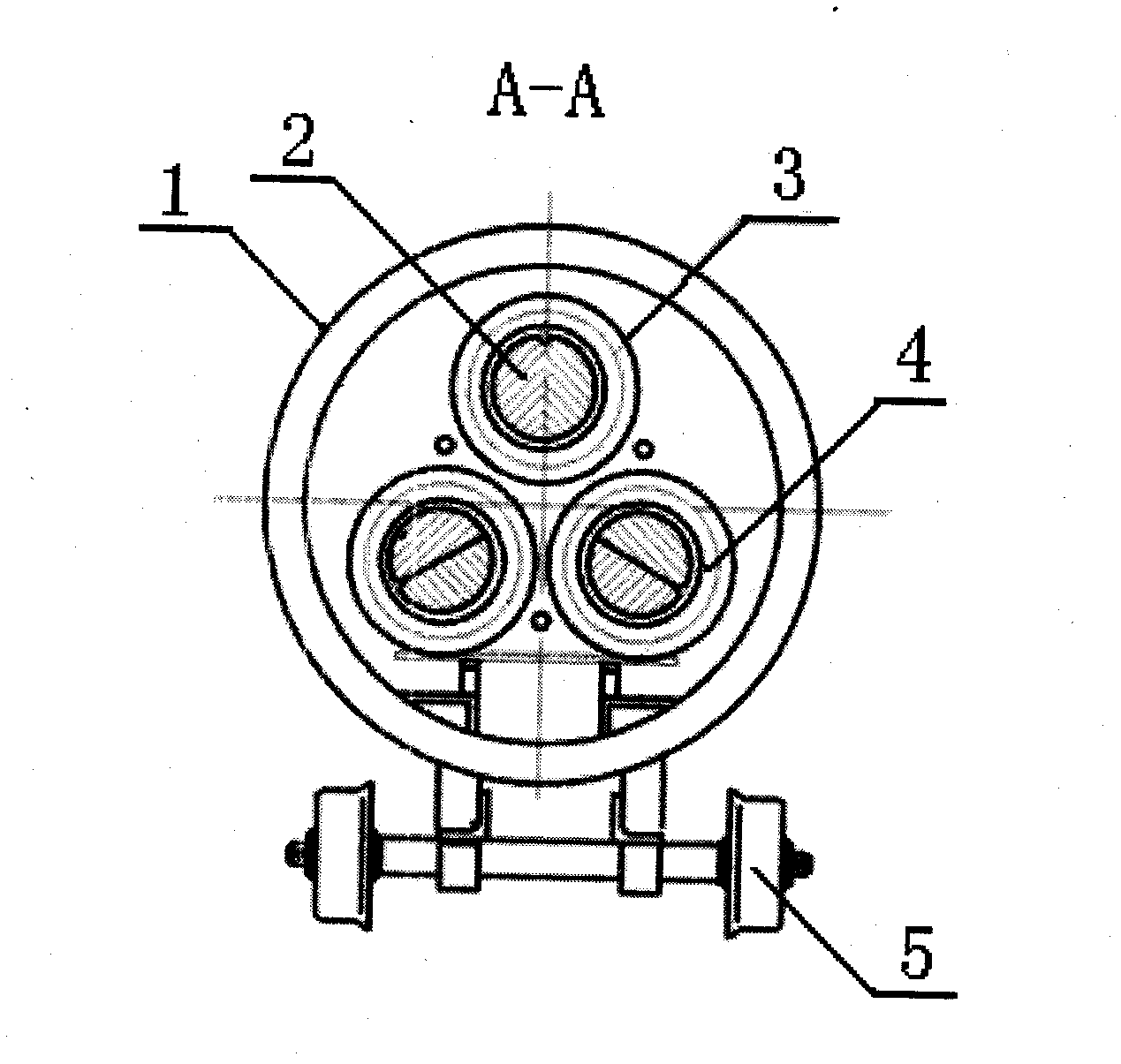
[0008] Specific implementation mode one: combine figure 1 , 2 The present embodiment will be described. The explosion-proof transformer for mining in this embodiment is composed of a flameproof casing 1, a three-phase wound core 2, a high-voltage coil 3 and a low-voltage coil 4. The three-phase wound core 2 is in the shape of a three-dimensional triangular wound core and is horizontally arranged on Inside the flameproof casing 1 , the low-voltage coil 4 is wound on the core column of the three-phase wound core 2 , and the high-voltage coil 3 is wound on the low-voltage coil 4 .
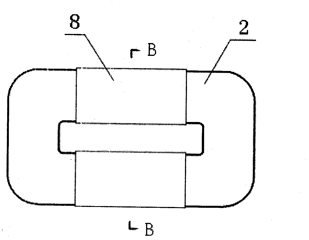
[0009] The three-phase wound core 2 is composed of three first single-frame cores 2-1, second single-frame cores 2-2 and third single-frame cores 2-3 with the same structure, and two adjacent single-frame cores The long sides are fixed together by binding bands 8 to form a three-dimensional triangular wound core. The first single frame core 2-1, the second single frame core 2-2 and the third single ...
specific Embodiment approach 2
[0010] Specific implementation mode two: combination figure 1 , 2 The present embodiment will be described. In the mine flameproof substation of this embodiment, the mine flameproof high voltage switch 6 and the mine flameproof low voltage switch 7 are arranged at the left and right ends of the flameproof shell 1, the mine flameproof high voltage switch 6 and the high voltage line The coils 3 and the mine flameproof low voltage switch 7 and the low voltage coil 4 are connected by wires.
specific Embodiment approach 3
[0011] Specific implementation mode three: combination figure 1 , 2 The present embodiment will be described. The difference between this embodiment and the first embodiment is that it also includes a roller 5 , and the roller 5 is arranged at the lower part of the flameproof casing 1 . Easy to move.
PUM
 Abstract
Description
Claims
Application Information
 - R&D
- Intellectual Property
- Life Sciences
- Materials
- Tech Scout
- Unparalleled Data Quality
- Higher Quality Content
- 60% Fewer Hallucinations
Browse by: Latest US Patents, China's latest patents, Technical Efficacy Thesaurus, Application Domain, Technology Topic, Popular Technical Reports.
© 2025 PatSnap. All rights reserved.Legal|Privacy policy|Modern Slavery Act Transparency Statement|Sitemap|About US| Contact US: help@patsnap.com


