Transformer DC (Direct Current) bias magnetic suppression device

A DC bias suppression, transformer technology, applied in circuit devices, emergency protection circuit devices, emergency protection circuit devices for limiting overcurrent/overvoltage, etc., can solve problems such as poor reliability and complex structure, and achieve reliability. High, large capacity, fast effect

Inactive Publication Date: 2012-10-03
ELECTRIC POWER RESEARCH INSTITUTE OF STATE GRID SHANDONG ELECTRIC POWER COMPANY +1
View PDF5 Cites 6 Cited by
  • Summary
  • Abstract
  • Description
  • Claims
  • Application Information

AI Technical Summary

Problems solved by technology

However, the existing bias suppression device requires an additional rectification circuit and thyristor shutdown circuit, which is relatively complex in structure and poor in reliability.

Method used


Image

  • Transformer DC (Direct Current) bias magnetic suppression device

Examples


Embodiment Construction

[0021] The present invention will be further described below in conjunction with the accompanying drawings and embodiments.

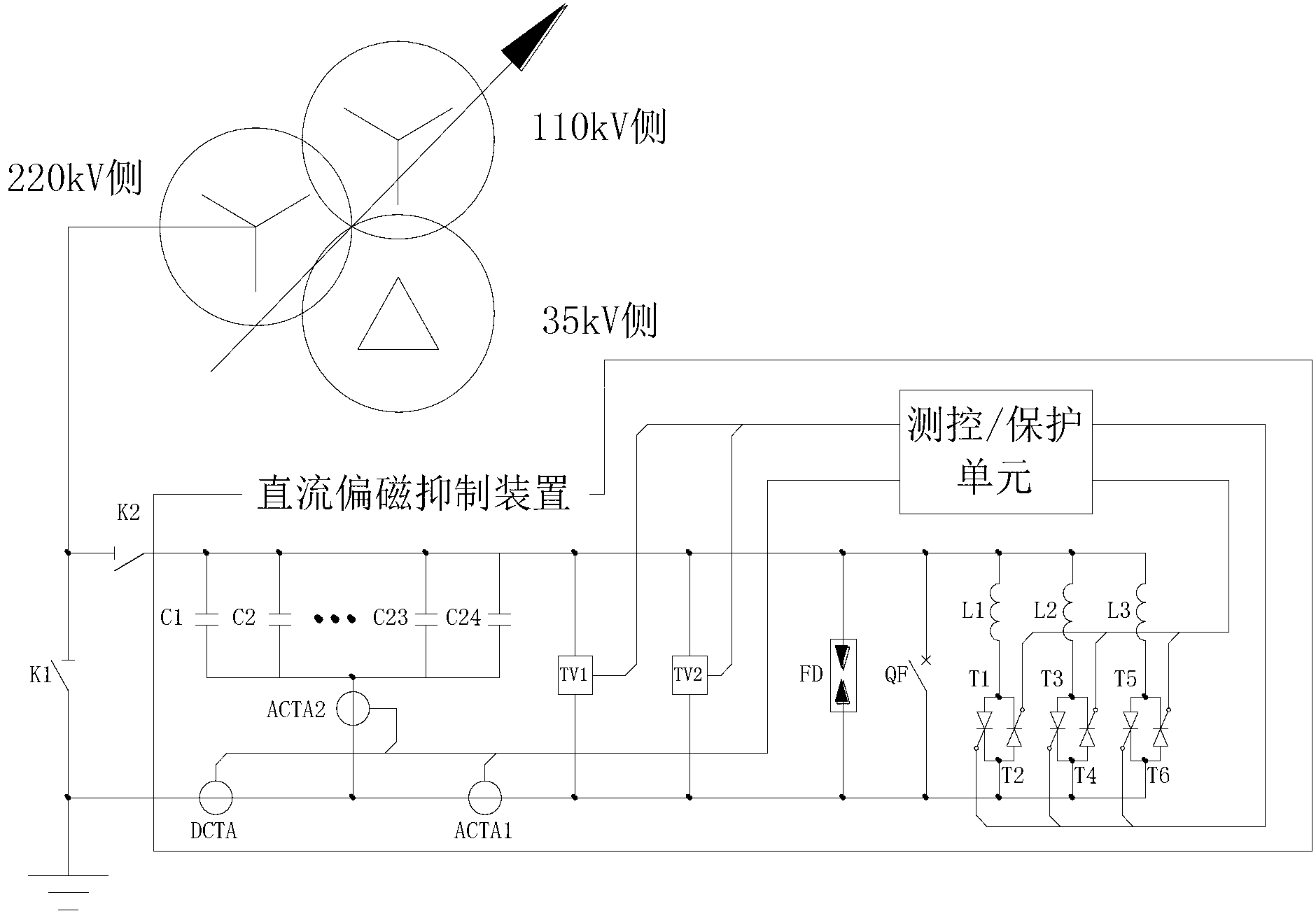
[0022] figure 1 Among them, K1 is the neutral point grounding switch of the transformer (original ground switch), and K2 is the device throwing knife switch (new ground switch, which is prepared by the customer). The device part includes: capacitor bank C1-C24, anti-parallel thyristor T1-T6 and its trigger circuit, reactor L1-L3, bypass mechanical switch QF, voltage transformer TV1-TV2, bypass switch current transformer ACTA1, Capacitive current transformer ACTA2, DC current transformer DCTA, discharge gap FD and measurement and control protection unit, etc.

[0023] The device has three working states, namely direct grounding state, capacitor grounding state and protection working state.

[0024] Directly grounded state: Bypass switch QF is closed, T1-T6 is disconnected, the capacitor is bypassed, and the neutral point of the transformer is directly ...


PUM


Abstract

The invention relates to a transformer DC (Direct Current) bias magnetic suppression device which comprises a group of capacitors which are connected in parallel. One parallel connection end of the capacitor group is connected in series with a capacitive current transformer ACTA2; the capacitive current transformer ACTA2 is connected with a DC current transformer DCTA and a bypass switch current transformer ACTA1 which are connected in series; voltage transformers TV1 and TV2, a discharging gap and a bypass mechanical switch QF are connected in parallel between the bypass switch current transformer ACTA1 and the other parallel connection end of the capacitor group; both ends of the bypass mechanical switch QF are also connected in parallel with reactors L1 to L3, thyristors T1 to T6 which are respectively connected in series with the reactors L1 to L3 and are reversely connected in parallel and a triggering circuit of the thyristors T1 to T6; and the DC current transformer DCTA, the bypass switch current transformer ACTA1, the voltage transformers TV1 and TV2 and the triggering circuit of the thyristors T1 to T6 are also connected with a measurement and control protection unit. The structure is simplified and the reliability and the intelligence of a system are improved.

Description

technical field [0001] The invention relates to a transformer DC bias suppression device. Background technique [0002] When the DC transmission system adopts the earth loop operation mode, the huge DC current flowing from the earth will have an impact on the nearby AC system, especially the relatively serious DC bias magnetic field on the transformer directly grounded at the neutral point, which not only increases the The reactive power consumption will affect the normal operation of the transformer, cause relay protection malfunction, and also cause a large increase in harmonics, which will have a greater impact on other electrical equipment, thus directly affecting the safe operation of substations and power plants. [0003] With the increasing number of high-voltage DC transmission projects in my country, the single-pole operation time of DC transmission projects and the total operation time of single-pole caused by the annual maintenance of DC transmission lines are als...

Claims


Application Information

Patent Timeline
Patent Type & Authority Applications(China)
IPC IPC(8): H02H9/00H02H9/04
Inventor 云玉新刘民姚金霞李贞王辉袁海燕
Owner ELECTRIC POWER RESEARCH INSTITUTE OF STATE GRID SHANDONG ELECTRIC POWER COMPANY
Why Eureka
Try Eureka